Topologi FTTH OLT: Membuat ODC dan ODP untuk Distribusi ke Client
Summary
TLDRIn this video, the speaker explains the setup of a fiber optic network topology, specifically focusing on connecting an OLT (Optical Line Terminal) to an ODC (Optical Distribution Cabinet) and then to an ODP (Optical Distribution Point). They discuss using passive splitters to distribute the fiber optic signal and measure signal attenuation along the network using an OPM. The video highlights a practical example of the signal's journey from the OLT through splitters and ODCs, eventually reaching client routers. The presenter encourages viewers to discuss improvements and offers downloadable network topology diagrams.
Takeaways
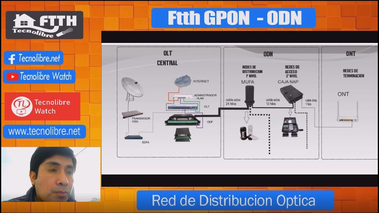
- 🔌 The video discusses a fiber optic network topology, specifically OLT (Optical Line Termination) setups and connections from OLT to ODC (Optical Distribution Cabinet) to ODP (Optical Distribution Point), then to the client's router or ONT (Optical Network Terminal).
- ⚙️ The presenter uses a passive splitter system for fiber optics without a ratio, and explains passive splitters versus ratio splitters.
- 📏 The signal loss (attenuation) is measured at various points in the network, starting at 8 dBm at the SFP (Small Form-factor Pluggable) module, reducing to 0.5 dBm after passing through the first splitter, and further decreasing through subsequent splits.
- 📡 The network layout includes multiple ODCs, such as an ODC at a central point (ODC Pusat), then branching to directional ODCs (e.g., ODC Barat for the west). Each ODC can connect to multiple ODPs for distributing the fiber connection closer to clients.
- 🔗 A 1:4 passive splitter is used at the central ODC, and a 1:8 splitter is used at the ODP, creating multiple pathways for connecting clients to the fiber optic network.
- 🔄 The topology allows for flexible routing, with the ability to branch out from a central ODC in all four directions (North, South, East, West), connecting more clients through additional ODPs.
- 🔧 The video provides practical tips on minimizing signal loss, such as using high-quality fiber cables, connectors, and considering environmental factors like cable bends.
- 📊 A theoretical formula is explained for calculating signal loss in passive splitters (1:4 adds around 7.5 dBm of loss, while 1:8 adds 10.5 dBm), but real-world results may vary due to cable and connector quality.
- 📈 The presenter demonstrates that the topology can support up to 128 client connections, though a single SFP can typically handle only 64 active connections at once.
- 💡 The topology is recommended for non-splitter setups, where maintaining signal quality is crucial, and signal loss needs to be kept under control for reliable client connections.
Q & A
What is the primary focus of the video script?
-The video script focuses on explaining the network topology for connecting an Optical Line Terminal (OLT) to Optical Distribution Cabinets (ODCs) and Optical Distribution Points (ODPs), eventually leading to the client’s router or Optical Network Terminal (ONT). It includes a practical demonstration using a passive splitter system without ratio adjustments.
What is an OLT, and what role does it play in the network topology?
-An OLT (Optical Line Terminal) is a device in a fiber-optic network that transmits data to multiple endpoints via optical fiber. It plays a central role in distributing optical signals to various ODCs and ODPs, which eventually connect to client devices.
What is the difference between ODC and ODP in this context?
-In this context, an ODC (Optical Distribution Cabinet) is used as an intermediary distribution point between the OLT and ODP. The ODP (Optical Distribution Point) is closer to the client, from which fiber optic cables lead to client routers or ONTs.
What is a passive splitter, and how is it used in the network?
-A passive splitter is a device that divides optical signals from one input into multiple outputs without needing power. In this setup, a 1:4 passive splitter is used to distribute the signal from the OLT to different ODCs, and a 1:8 splitter is used to further distribute the signal from the ODP to multiple client routers.
How does the script explain signal attenuation across the network?
-The script explains that as the signal travels from the OLT through the passive splitters and fiber cables, signal loss or attenuation occurs. For example, the signal from the OLT starts at 8 dBm and experiences losses through splitters and cables, resulting in a final signal strength of around -18 dBm at the client’s ONT.
Why is the OPM (Optical Power Meter) reading relevant, and what did it show in the video?
-The OPM is relevant because it measures the signal strength (in dBm) at different points in the network. The video demonstrates an initial reading of 3.7 dBm at the OLT, which reduces after each passive splitter and connection point, showing how attenuation affects the signal.
What does the term '1:4' or '1:8' refer to in passive splitters?
-The terms '1:4' or '1:8' refer to the ratio of inputs to outputs in a passive splitter. A 1:4 splitter takes one input and splits it into four outputs, while a 1:8 splitter divides one input into eight outputs, distributing the optical signal to multiple destinations.
How does the script describe the layout of the ODC and ODP in terms of geographical directions?
-The script explains that the ODC can be configured to distribute signals in four geographical directions: north, south, east, and west. Each direction can connect to multiple ODPs, allowing for flexible network expansion.
What is the significance of signal strength -18 dBm in this network setup?
-The signal strength of -18 dBm at the client’s ONT is significant because it indicates that the signal is still within an acceptable range for operation, even after passing through multiple ODCs, ODPs, and splitters. This strength is close to the theoretical calculations presented in the video.
How can this network topology scale to accommodate more clients?
-This network topology can scale by adding more ODCs and ODPs in different directions (north, south, east, west), each connecting multiple clients via splitters. A single OLT, through the use of passive splitters, can support up to 128 clients, though typically, only 64 clients are actively connected to each OLT.
Outlines

此内容仅限付费用户访问。 请升级后访问。
立即升级Mindmap

此内容仅限付费用户访问。 请升级后访问。
立即升级Keywords

此内容仅限付费用户访问。 请升级后访问。
立即升级Highlights

此内容仅限付费用户访问。 请升级后访问。
立即升级Transcripts

此内容仅限付费用户访问。 请升级后访问。
立即升级浏览更多相关视频
ODN ( Optical Distribution Network ) Red de distribución óptica

Jaringan Fiber Optic : Topologi Fiber To THe Home (FTTH) dasar

20_1 Perancangan Topologi Jaringan FTTH
Konfigurasi Mikrotik untuk OLT + Setting EPON OLT Mode PPPoE dan Hotspot
Cara Setting OLT GPON Tanpa VLAN Langsung Plug n Play ONT ke Mikrotik

CARA MEMBUAT SERVER INTERNET DENGAN PROXMOX, MIKROTIK, OLT , SWITCH MANAGED
5.0 / 5 (0 votes)
