Understanding the Area Moment of Inertia
Summary
TLDRThis video script explores the concept of area moment of inertia, crucial for understanding a structure's resistance to bending. It explains how material distribution in a cross-section affects stiffness, introduces the calculation of area moment of inertia through integration, and highlights the I-beam's efficiency. The script also covers the parallel axis theorem for calculating moments of inertia for non-centroidal axes and distinguishes between area and mass moments of inertia. Practical applications in beam and column analysis are discussed, including the use of flexural rigidity and the radius of gyration.
Takeaways
- 🌟 The stiffness of a plank of wood is greater when the load is applied to the shorter side of its rectangular cross-section.
- 📏 The area moment of inertia (I) quantifies a cross-section's resistance to bending and is calculated based on how the area is distributed relative to a bending axis.
- 🏗️ I-beams are efficient at resisting bending because they position most of the material far from the bending axis.
- 📐 The area moment of inertia is not unique to a cross-section and varies depending on the axis of bending.
- 🧩 Area moment of inertia can be approximated by dividing a cross-section into small elements, each contributing to the total based on its area and distance from the axis.
- ✏️ The area moment of inertia is precisely defined using integration, with the result denoted by I and subscripted by the reference axis.
- 📘 Reference texts often provide area moment of inertia equations for centroidal axes, which pass through the centroid of the cross-section.
- 🔄 The parallel axis theorem allows calculating the area moment of inertia for any axis parallel to a centroidal axis by adding the moment of inertia of the centroidal axis to the product of the area and the square of the distance between the axes.
- 🔢 The area moment of inertia is crucial for analyzing beams and columns, appearing in equations that define deflection and critical buckling load.
- 🔄 The radius of gyration represents the distance at which the area of a cross-section can be condensed into a strip to maintain the same moment of inertia, and it is calculated based on the area moment of inertia.
- 🔄 The polar moment of inertia (J) represents the resistance to twisting and is calculated using a reference axis perpendicular to the cross-section plane.
Q & A
Why is it more efficient to apply load to the shorter side of a rectangular cross-section?
-Applying load to the shorter side of a rectangular cross-section is more efficient because it distributes the material closer to the bending axis, which increases the resistance to bending and makes the plank stiffer.
What is the area moment of inertia and why is it important?
-The area moment of inertia is a measure of a cross-section's resistance to bending, quantifying how the area is distributed relative to a particular axis. It's important in structural engineering as it helps to predict how materials will behave under bending loads.
How does the distance of material from the bending axis affect the stiffness of a cross-section?
-The further the material is spread from the bending axis, the stiffer the cross-section tends to be. This is because the moment of inertia increases with the square of the distance from the axis, enhancing the section's resistance to bending.
Why is the I-beam an efficient cross-section for construction?
-The I-beam is efficient because it locates the majority of the material as far as possible from the bending axis, which maximizes the area moment of inertia and thus the resistance to bending for a given amount of material.
How is the area moment of inertia calculated for an arbitrary cross-section?
-The area moment of inertia for an arbitrary cross-section can be calculated by integrating the quantity equal to the area of each small element (dA) multiplied by the square of its distance (Y^2) from the reference axis.
What is the unit of area moment of inertia and why is it always positive?
-The unit of area moment of inertia is length to the fourth power. It is always positive because it involves the square of distances, which are inherently non-negative.
How do you calculate the area moment of inertia for a rectangular cross-section?
-For a rectangular cross-section, the area moment of inertia (I-X) about the centroidal axis can be calculated using the integral of b*dy*(y^2) from -h/2 to h/2, resulting in I-X = b*h^3/12.
What is the parallel axis theorem and how is it used?
-The parallel axis theorem allows for the calculation of the area moment of inertia for any axis parallel to a known centroidal axis by summing the moment of inertia about the centroidal axis and the product of the cross-sectional area and the square of the distance between the axes.
Why is the area moment of inertia different for different axes?
-The area moment of inertia is not a unique property of a cross-section; it varies depending on the axis about which the bending is considered. Different axes will have different distances from the material's centroid, affecting the calculated moment of inertia.
How can the area moment of inertia be used to analyze beams and columns?
-The area moment of inertia is used in the analysis of beams and columns to calculate deflection, flexural rigidity, and critical buckling load. It represents the resistance due to the geometry of the beam cross-section to bending.
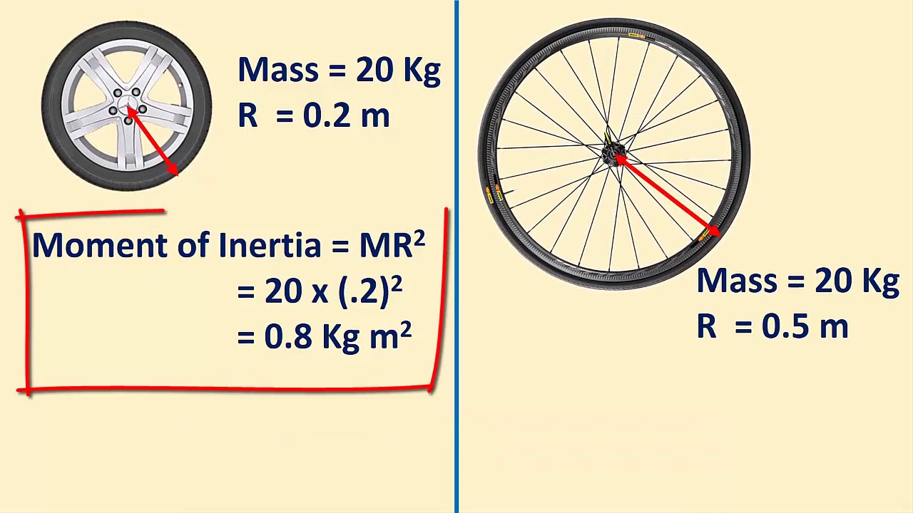
What is the difference between area moment of inertia and mass moment of inertia?
-Area moment of inertia is a geometric property that describes a shape's resistance to bending, while mass moment of inertia is a measure of an object's resistance to changes in rotational velocity. They have different units and uses.
What is the polar moment of inertia and how is it calculated?
-The polar moment of inertia (J) represents the resistance of a cross-section to twisting about a reference axis perpendicular to the plane of the cross-section. It is calculated using integration with the distance (Rho) to the axis, and can be found using the perpendicular axis theorem as J = I-X + I-Y.
Outlines
🛠️ Introduction to Area Moment of Inertia
This paragraph introduces the concept of area moment of inertia, a measure of a cross-section's resistance to bending. It explains how a plank's stiffness varies depending on the load application point and how the distribution of material relative to the bending axis affects stiffness. The area moment of inertia quantifies this resistance, with I-beams being an efficient design due to their material distribution. The paragraph also discusses how to calculate the area moment of inertia for arbitrary cross-sections using integration, and how the value changes based on the reference axis. It concludes with an example calculation for a rectangular cross-section and mentions the use of reference texts for common shapes.
📐 Calculation and Application of Area Moment of Inertia
The second paragraph delves into calculating the area moment of inertia for a rectangular cross-section using the parallel axis theorem. It discusses the addition and subtraction of area moments of inertia and the importance of using the correct reference axis for calculations. The paragraph also clarifies the difference between area and mass moment of inertia, emphasizing their distinct uses and units. It highlights the significance of area moment of inertia in beam and column analysis, introducing concepts like flexural rigidity, deflection, and critical buckling load. Additionally, it mentions the radius of gyration and polar moment of inertia, which are related to the resistance to twisting and are calculated similarly to the moments of inertia about the X and Y axes.
🔄 Transformation of Reference Axes and Product of Inertia
The final paragraph explores the transformation of reference axes and the concept of product of inertia. It explains how moments of inertia for rotated axes can be calculated using transformation equations, and how the product of inertia is calculated. The paragraph draws a parallel between the transformation of stresses and moments of inertia, noting that both are tensor quantities. It mentions the use of Mohr's circle for determining principal moments of inertia for any angle of rotation. The summary concludes with a brief invitation to subscribe, reflecting the educational and engaging nature of the video script.
Mindmap
Keywords
💡Stiffness
💡Cross-section
💡Area Moment of Inertia
💡I-beam
💡Centroid
💡Deflection
💡Flexural Rigidity
💡Parallel Axis Theorem
💡Radius of Gyration
💡Polar Moment of Inertia
💡Transformation of Axes
Highlights
The plank's stiffness varies depending on how it's oriented relative to the load.
Cross-sections with material further from the bending axis are stiffer.
Area moment of inertia quantifies a cross-section's resistance to bending.
I-beams are efficient at resisting bending due to their design.
Area moment of inertia is not unique and depends on the axis of bending.
Small elements' contribution to area moment of inertia is calculated by multiplying area dA by Y^2.
Area moment of inertia, denoted by I, is always positive due to the squared term.
Rectangular cross-section's I-X can be calculated using integration.
I-Y for a rectangle is derived by swapping height and width terms.
Area moment of inertia equations are often provided for centroidal axes in reference texts.
Parallel axis theorem allows calculating moments of inertia for any parallel axes.
Area moments of inertia can be added or subtracted for composite shapes.
The parallel axis theorem is essential for calculating moments of inertia of composite shapes.
Area moment of inertia should not be confused with mass moment of inertia.
Area moment of inertia is crucial for analyzing beams and columns.
Flexural rigidity, E-I, is a key parameter in beam and column analysis.
Radius of gyration represents the theoretical distance to condense the area's moment of inertia.
Polar moment of inertia, J, represents resistance to twisting and is calculated similarly to I-X and I-Y.
The perpendicular axis theorem states J equals I-X plus I-Y.
Transformation equations can calculate moments of inertia for rotated axes.
Area moment of inertia is a tensor quantity, similar to stress.
Mohr's circle can determine principal moments of inertia for rotated axes.
Transcripts
Let's say we have a plank of wood which we would like to use to cross a canal.
It has a rectangular cross-section and so we could either use it like we have done here,
or we could rotate it onto its side, like this.
Intuitively we can tell that the plank will be stiffer if the load is applied to the shorter
side of the cross-section.
Some cross-sections are much more efficient at resisting bending than others.
The further the material is spread from the bending axis, the stiffer a cross-section
tends to be.
The cross-section on the right has more material located far from the bending axis and so is
better at resisting bending, even though both cross-sections have the same area.
This concept of resistance to bending can be quantified by calculating the area moment
of inertia, which is also sometimes called the second moment of area.
The area moment of inertia reflects how the area of a cross-section is distributed relative
to a particular axis, and so is a measure of how much resistance the cross-section has
to bending.
The I-beam locates the majority of the material as far as possible from the bending axis,
and so is a very efficient cross-section.
This is why it is so commonly used in construction.
In this video we're going to take a detailed look at the area moment of inertia.
Let's start by seeing how it can be calculated for an arbitrary cross-section like the one
shown here.
The first thing to note is that the area moment of inertia is not a unique property of a cross-section.
It quantifies the resistance to bending about a particular axis, and so its value changes
depending on where we place this reference axis.
We can approximate the area moment of inertia of a cross-section by splitting it into small
elements.
Each element contributes to the total area moment of inertia by a quantity equal to its
area dA multiplied by Y^2, where Y is the distance to the reference axis,
which is the X axis in this case.
We can sum up the values for all of the small elements to obtain the area moment of inertia
for the entire cross-section.
It is denoted by the letter I, and because the X axis is our reference axis, we will
give it the subscript X.
We can define the area moment of inertia more precisely using integration, like this.
And if the Y axis is our reference axis, we can calculate I-Y in the same way.
The area moment of inertia has the unit of length to the fourth power, and because of
the squared term it is always a positive quantity.
Let's work through an example where we calculate the I-X and I-Y values for a rectangular cross-section,
using those equations.
We can consider that the rectangle is made up of multiple thin strips which each have
a height equal to dy.
Each strip has an area equal to b * dy, which gives us the following integral.
The limits of the integral are from the bottom to the top of the rectangle, so from negative
h over 2, to h over 2.
If we solve this definite integral we end up with I-X being equal to b multiplied by
h to the power 3, divided by 12.
We can obtain the equation for I-Y by switching the height and the width terms.
So there you go, we just calculated the area moment of inertia for a rectangular cross-section
using integration.
But calculating integrals can be difficult, so to help us out area moment of inertia equations
are often provided in reference texts for a range of common shapes.
A few examples are shown here.
Usually the equations are provided for centroidal axes, which are axes that pass through the
centroid of the cross section.
Remember that the centroid is the geometric centre of a cross-section.
X-C and Y-C are called the centroidal axes.
So what do we do if we need to obtain an area moment of inertia equation for an axis that
is not a centroidal axis, but it is too difficult to calculate it using integration?
Fortunately there is a method we can use to calculate an adjusted area moment of inertia
for any axis that is parallel to a centroidal axis, like this one.
The adjusted area moment of inertia I-X can be calculated by summing the moment of inertia
of the centroidal axis, and the product of the cross-sectional area A and the square
of distance d between both axes.
This is called the parallel axis theorem.
It's useful because we can take the equations found in reference texts for centroidal axes
and adjust them to obtain the moments of inertia for any parallel axes.
Let's look at an example.
Earlier we determined an equation for the area moment of inertia of a rectangular cross-section,
about an axis passing through the centroid of the rectangle.
We can use the parallel axis theorem to calculate I for an axis shifted to the bottom of the
cross-section.
All we have to do is take the equation for I we derived earlier, and add the area of
the rectangle b*h multiplied by the distance h over 2, squared.
One useful property of area moments of inertia is that they can be added to and subtracted
from each other.
This means we can calculate the value of I for a shape like this by taking I for section
A and subtracting I for section B.
If we are calculating I based on equations, we need to make sure that the equations we
are using correspond to the correct reference axis.
In the case of this T section for example, we can't just add the I values for two rectangles
given in a textbook because these equations are for centroidal axes only, and the reference
axis doesn't pass through the centroid of the top rectangle.
Fortunately we can use the parallel axis theorem to overcome this.
If h and b are the height and the width of the rectangles, the distance between the reference
axis and the centroid of rectangle 2 is (h1+h2)/2.
We can calculate I for the composite cross-section using the parallel axis theorem, like this.
This is another reason the parallel axis theorem is really important.
It gives us an easy way to calculate area moments of inertia for all sorts of different
composite shapes.
It's worth clarifying at this point that the area moment of inertia should not be confused
with the mass moment of inertia, which is a parameter used to describe the resistance
of a body to changes in rotational velocity.
There are similarities in the way the two parameters are calculated, but they have different
units and completely different uses.
So, when might you actually need to use the area moment of inertia?
Well it is a particularly important parameter for the analysis of beams and columns.
This equation, for example, defines the deflection of a beam for an applied bending moment M.
You will notice that the term E-I appears in many equations.
It is called "flexural rigidity".
It quantifies the resistance of a beam to bending.
As we have just seen, I is the resistance due to the geometry of the beam cross-section.
But the stiffness of the beam material also contributes to its total resistance to bending,
and is captured by Young's modulus E. Flexural rigidity also appears in the analysis
of columns, where it can be used to calculate the critical buckling load.
Another important parameter related to the area moment of inertia that appears in the
analysis of columns is the radius of gyration.
It represents the theoretical distance at which we could condense the entire area of
a cross-section into a narrow strip, to get the same moment of inertia as the original
cross-section.
It can be calculated using this equation.
So far we have only calculated the area moments of inertia relative to the X and Y axes.
We can calculate a third area moment of inertia for a reference axis that is perpendicular
to the plane of the cross-section.
This quantity is called the polar moment of inertia, and it is usually denoted using the
letter J. It represents the resistance of the cross-section to twisting about the reference
axis.
It is calculated in the same way as I-X and I-Y, but using the distance Rho to the axis,
rather than the perpendicular distance to the X or Y axes.
We can calculate J using integration, like this.
Rho squared is equal to X squared plus Y squared, so we can expand the equation.
And by doing a little more work we can figure out that J is equal to I-X plus I-Y.
This is known as the perpendicular axis theorem.
The polar moment of inertia is mainly relevant for situations which involve torsion.
Check out my video on torsion if you want to learn more about this.
To fully master the area moment of inertia there is one last thing we need to cover,
which is the rotation of the reference axes.
We can use the transformation equations shown here to calculate moments of inertia for rotated
axes.
The I-X-Y term in these equations is the product of inertia, and it is calculated using this
equation.
Rotating the reference axes works in a very similar way to transformation of stresses,
which I covered in a video on stress transformation.
This is because like stress, the area moment of inertia is a tensor quantity.
In fact you can even use Mohr's circle to determine moments of inertia for rotated axes,
like you can with stresses.
It has I on the horizontal axis, and the product of inertia I-XY on the vertical axis.
You can use Mohr's circle to find the principal moments of inertia, which are the maximum
and minimum values for any angle of rotation.
That's it for what ended up being quite a detailed review of the area moment of inertia.
Thanks for watching, and don't forget to subscribe if you haven't already!
5.0 / 5 (0 votes)