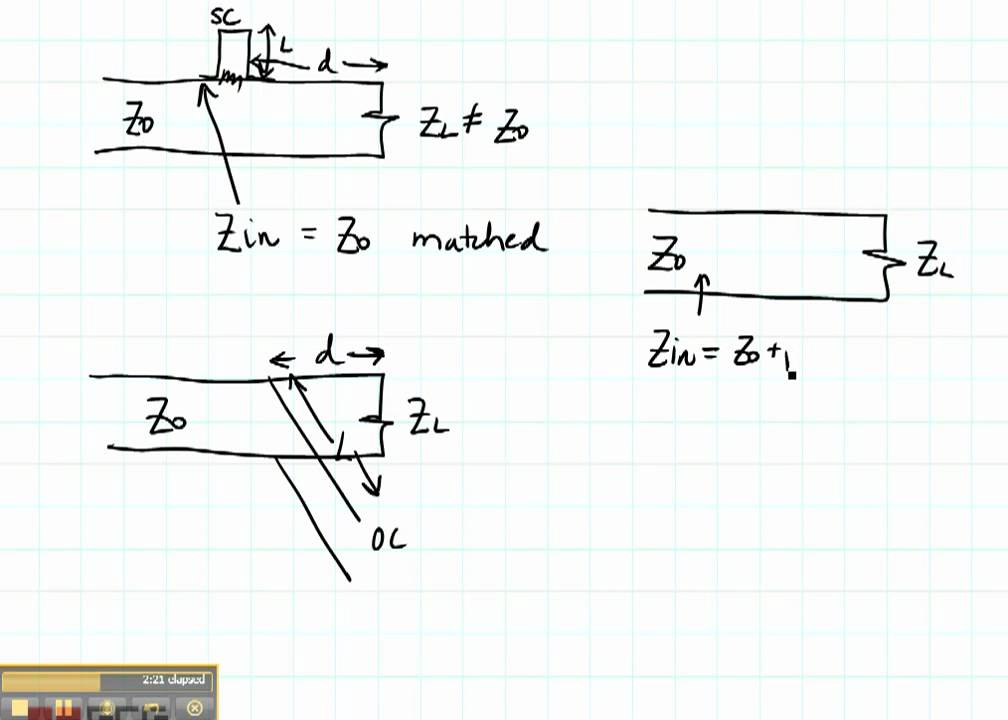
ECE3300 Lecture 13b-8 Impedance Matching stub match parallel
Summary
TLDRThe script describes a process for matching impedance using a parallel stub match with a short-circuit on the end. It starts by normalizing and plotting ZL on a Smith chart, then converting to admittance (YL) and rotating to match the real part. The script then calculates the length of the stub needed for matching, using the Smith chart to determine the imaginary part and the distance to the short-circuit point, ultimately providing the required lengths for the stub.
Takeaways
- 🔍 The video discusses a method for matching impedance using a parallel stub on a Smith chart.
- 📏 The process starts with normalizing and plotting the load impedance ZL, which is 2 + j2 in this case.
- 🔄 The impedance ZL is then converted to admittance YL by translating it through the center of the Smith chart.
- 🎯 The goal is to rotate YL to match the real part of the impedance to the generator, which is set to 1 in this scenario.
- 📐 The rotation is visualized using a matching circle on the Smith chart, and a protractor or paper is suggested for precise measurement.
- 📍 Two potential YA points (YA-1 and YA-2) are identified, with YA-1 chosen for the shortest distance to the generator.
- 🌐 The distance D is calculated by adding the lengths of the segments from the center to YA-1 and then to the matching circle.
- 📉 The imaginary part of YA is measured to be approximately 1.6, which is then used to determine the Y stub value.
- 🔄 The Y stub is adjusted to -1.6 to create a short-circuit condition at the end of the stub.
- 📏 The final distance L is calculated by subtracting the value at the short-circuit point (0.165 wavelengths) from the total distance to the generator (0.25 wavelengths).
Q & A
What is a stub match in the context of the provided script?
-A stub match refers to a technique in radio frequency (RF) engineering where a short section of transmission line, or 'stub', is used to match the impedance of a load to the source impedance for optimal power transfer.
What is the purpose of normalizing and plotting ZL?
-Normalizing and plotting ZL is a method used to represent the load impedance (ZL) on a Smith chart, which helps in visualizing and calculating the impedance matching process.
Why is it beneficial to convert ZL to admittance (YL) in this scenario?
-Converting ZL to admittance (YL) simplifies the process of adding a parallel stub because it allows for easier manipulation of the impedance on the Smith chart, especially when dealing with parallel elements.
What does the matching circle on the Smith chart represent?
-The matching circle on the Smith chart represents the constant resistance circle where the real part of the impedance is equal to the characteristic impedance of the transmission line.
Why is the shortest distance chosen for YA?
-The shortest distance is chosen for YA to minimize the physical length of the stub, which is desirable for practical reasons such as minimizing the size and potential losses in the RF system.
What is the significance of the distance D mentioned in the script?
-Distance D represents the physical length of the transmission line needed to achieve the desired impedance match, calculated from the Smith chart after rotating to the matching circle.
How does the script suggest finding the imaginary part to match?
-The script suggests finding the imaginary part to match by reading off the imaginary part of YA, adjusting it to the desired value (in this case, to -1.6), and then rotating towards the load to find the short-circuit admittance.
What does YA-1 and YA-2 represent?
-YA-1 and YA-2 represent two possible positions on the Smith chart where the real part of the admittance is matched. YA-1 is chosen for being the shortest path.
Why is it important to match both the real and imaginary parts of the impedance?
-Matching both the real and imaginary parts of the impedance ensures that the load is perfectly matched to the source, maximizing power transfer and minimizing reflections.
What is the significance of the term 'Y stub' in the script?
-The term 'Y stub' refers to the admittance at the input of the stub. It is calculated to achieve the desired impedance matching condition, where the imaginary part is adjusted to match the load.
How does the script suggest determining the length of the parallel stub?
-The script suggests determining the length of the parallel stub by rotating the admittance point towards the load (Y short-circuit) on the Smith chart and reading the corresponding distance from the chart.
Outlines

此内容仅限付费用户访问。 请升级后访问。
立即升级Mindmap

此内容仅限付费用户访问。 请升级后访问。
立即升级Keywords

此内容仅限付费用户访问。 请升级后访问。
立即升级Highlights

此内容仅限付费用户访问。 请升级后访问。
立即升级Transcripts

此内容仅限付费用户访问。 请升级后访问。
立即升级浏览更多相关视频

ECE3300 Lecture 13b-1 Impedance Matching Intro

wien bridge |frequency measurement by Wien bridge | Wiens bridge in hindi | wien's bridge | formula

Types Of Circuits | Series Circuit | Parallel Circuit | Electricity UNIT(PART-5) | Grade-7,8

NUEVO PAN CONTROL vs MOD ANTERIOR

ECE3300 Lecture 6-3 Lossless Transmission Lines reflection coefficient

The RF Class C amplifier - basics and simulations (1/2)
5.0 / 5 (0 votes)
