Basic Electricity - Resistance and Ohm's law

Afrotechmods
7 Nov 201609:10

Summary

TLDRThis educational video delves into the concept of electrical resistance and Ohm's Law, crucial for safely incorporating LEDs into circuits. It explains how resistors, available in various forms, control current flow by converting kinetic energy into heat due to atomic collisions. The script teaches how to read resistor color codes and apply Ohm's Law (V=IR) to calculate the appropriate resistor value for an LED circuit. Practical examples, such as calculating a 1000-ohm resistor for a 10V source with a 10mA limit, are provided. The video also touches on the importance of staying within component voltage limits to prevent damage.

Takeaways

  • πŸ”Œ Electrical resistance is crucial for controlling the flow of current in a circuit, and resistors are devices designed to provide this resistance.
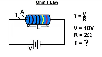
  • 🌑 Ohm's Law (V=IR) is the fundamental principle that relates voltage, current, and resistance in electrical circuits.
  • πŸ” Different types of resistors exist, from basic hobbyist resistors to tiny surface mount resistors found in devices like smartphones, and large power supply resistors.
  • 🌟 The resistance in a material occurs due to the inefficient movement of electrons, which can be caused by atomic vibrations or unsuitable atomic arrangements.
  • ⚑ Resistance is measured in ohms (Ξ©), with very low resistance under 1 ohm and very high resistance around 1 megaohm.
  • πŸ›  A multimeter is a tool that can measure the resistance of almost any material.
  • 🎨 Resistors often have colored bands that represent their resistance value, which can be decoded using a color code or a resistor calculator app.
  • βš™οΈ By selecting resistors with specific values, one can control the amount of current flowing through a circuit, such as in an LED setup.
  • πŸ’‘ LEDs require a specific forward voltage and current to operate safely, and resistors are used to limit the current to this safe level.
  • πŸ”† Ohm's Law can be rearranged algebraically to solve for any of the variables (voltage, current, resistance) if the other two are known.
  • πŸ”₯ Exceeding the recommended voltage for electronic components can lead to sudden failure or damage.
  • πŸ“ The equation for calculating the resistor value for an LED circuit is derived from Ohm's Law, but there are limitations to its application at very high voltages.

Q & A

  • What is the main purpose of a resistor in an electrical circuit?

    -The main purpose of a resistor is to limit and control the flow of electrical current in a circuit, preventing components like LEDs from receiving too much current and getting damaged.

  • Why did the LED blow up when connected directly to 7.5V in the example provided?

    -The LED blew up because the voltage was too high, causing an excessive amount of current to flow through it, exceeding the LED's safe operating limits.

  • What is the fundamental principle behind how resistors work?

    -Resistors work based on the principle that as electrons move through a material, they sometimes collide with atoms that are in the way, causing the flow of current to be resisted and some of the kinetic energy to be converted into heat.

  • What is the unit of measurement for electrical resistance?

    -The unit of measurement for electrical resistance is the ohm, symbolized by the Greek letter omega (Ξ©).

  • What does the color code on resistors represent and how can it be used?

    -The color code on resistors represents their resistance value. Each color corresponds to a specific number, and the sequence of colors can be translated into a resistance value using a resistor color code chart or a calculator app.

  • What is Ohm's Law and how is it used in calculating the resistance needed for an LED circuit?

    -Ohm's Law is the fundamental relationship between voltage (V), current (I), and resistance (R), expressed as V = I * R. It can be rearranged to calculate any of these variables if the other two are known. In an LED circuit, it is used to determine the appropriate resistance value needed to achieve a desired current flow.

  • Why is it important to consider the tolerance of a resistor?

    -The tolerance of a resistor indicates the possible variation in its resistance value from the nominal value. It is important because a real-world resistor might have a resistance slightly higher or lower than its rated value, and for most home circuits, a tolerance of +/- 5% is usually sufficient.

  • What happens when the voltage across a resistor is doubled while keeping the resistance constant?

    -According to Ohm's Law, if the voltage across a resistor is doubled and the resistance remains constant, the current flowing through the resistor will also double.

  • How does the polarity of a resistor differ from that of an LED in a circuit?

    -The polarity of a resistor does not matter in a circuit, meaning it can be connected in either direction. In contrast, the polarity of an LED is crucial, as it must be connected with the correct polarity to function properly.

  • What is the recommended maximum current for the LED used in the script's example circuit?

    -The recommended maximum current for the LED in the example circuit is 20mA.

  • Why did the resistor get too hot when connected to a 140V power supply?

    -The resistor got too hot because the voltage was significantly higher than what the resistor and LED circuit were designed for. This resulted in a higher current flow than the resistor could safely handle, leading to overheating.

Outlines

00:00

πŸ”Œ Understanding Electrical Resistance and Resistors

The first paragraph introduces the concept of electrical resistance and its importance in controlling current flow in circuits. It explains how a resistor acts as a device to resist the flow of electrical current, preventing damage to components like LEDs. The video provides examples of different types of resistors and their applications. It delves into the atomic explanation of resistance, where electrons bump into vibrating atoms, converting kinetic energy into heat. The paragraph also covers the measurement of resistance in ohms, the color code for resistors, and the use of Ohm's law (V=I*R) to calculate the necessary resistance for a circuit. The summary emphasizes the practical application of resistors in limiting current for an LED circuit and the importance of understanding Ohm's law for circuit design.

05:01

πŸ”§ Applying Ohm's Law to LED Circuits

The second paragraph focuses on applying Ohm's law to LED circuits, explaining how to calculate the appropriate resistor value to limit the current and prevent component damage. It demonstrates the linear relationship of Ohm's law, where doubling the voltage results in doubling the current through a fixed resistor. The paragraph provides a step-by-step example of calculating the resistor needed for a 9-volt battery and a white LED with a specified forward voltage and maximum current. It also highlights the practical aspects of circuit building, such as the tolerance of resistors and the effect of different resistor values on LED brightness. The summary concludes with a cautionary note about the limitations of Ohm's law and a teaser for the next video on electrical power, hinting at the importance of understanding power dissipation in resistors.

Mindmap

Keywords

πŸ’‘Electrical Resistance

Electrical resistance is the opposition to the flow of electric current through a material. It is a fundamental concept in the video, as it explains how resistors are used to control and limit the current in an LED circuit. The script uses the analogy of a 'pushing force' to describe voltage and how resistance acts to counteract this force, preventing excessive current flow that could damage components like LEDs.

πŸ’‘Ohm's Law

Ohm's Law is a basic principle in electrical engineering that relates voltage, current, and resistance in a simple formula: V=I*R, where V is voltage, I is current, and R is resistance. The video emphasizes Ohm's Law as the mathematical relationship necessary to calculate the appropriate resistor value for an LED circuit, ensuring the LED operates within its safe current limits.

πŸ’‘Resistor

A resistor is an electronic component designed to introduce resistance into a circuit. The script describes different types of resistors, such as through-hole and surface mount, and their applications in various devices. Resistors are crucial in the video's context for limiting the current in an LED circuit to prevent damage to the LED.

πŸ’‘LED Circuit

An LED circuit is a specific type of electrical circuit that includes a light-emitting diode (LED) which lights up when current flows through it. The video script discusses how to safely incorporate an LED into a circuit using a resistor to limit the current, ensuring the LED operates within its specified parameters and does not blow up due to excessive current.

πŸ’‘Current

In the context of the video, current refers to the flow of electric charge, typically measured in amperes (A). The script explains the importance of controlling current to prevent damage to components like LEDs, using the concept of electrons 'jumping' from atom to atom and the resistance they encounter, which can convert kinetic energy into heat.

πŸ’‘Voltage

Voltage is the electrical potential difference between two points in a circuit, which can be thought of as the 'pushing force' that drives the current. The video script uses the example of connecting an LED directly to a 7.5V source to illustrate the dangers of high voltage without proper resistance, leading to excessive current and component failure.

πŸ’‘Ohms

Ohms is the unit of electrical resistance, symbolized by the Greek letter omega (Ξ©). The script provides a scale for understanding resistance values, from under 1 ohm for good conductors to 1 megaohm for poor conductors, and how these values are crucial for selecting the correct resistor for an LED circuit.

πŸ’‘Resistor Color Code

The resistor color code is a system used to identify the resistance value of a resistor by its colored bands. The video script mentions a specific example of a resistor with red, violet, brown, and gold bands, which corresponds to a 270 ohm resistor. This code is essential for selecting the correct resistor for a circuit without needing to measure its resistance.

πŸ’‘Multimeter

A multimeter is a versatile electronic measuring instrument that can measure various electrical properties, including resistance. The script introduces the multimeter as a tool for measuring resistance, which is important for verifying the correct resistance value in a circuit and ensuring safe operation.

πŸ’‘Tolerance

Tolerance in the context of resistors refers to the permissible variation in the resistance value from the specified standard. The script explains that a real-world 1000 ohm resistor might have a resistance of 1020 ohms or 998 ohms, indicating a tolerance level. Understanding tolerance is important for designing circuits that account for variability in component values.

πŸ’‘Polarity

Polarity refers to the orientation of electrical terminals, with positive and negative designations. The video script clarifies that while the polarity matters for LEDs, it does not for resistors, meaning resistors can be connected in either direction in a circuit without affecting their operation.

Highlights

Introduction to electrical resistance and its role in controlling current flow in circuits.

Explanation of how voltage can act as a pushing force for electric current.

Importance of resistors in preventing excessive current flow and potential damage to components like LEDs.

Different types of resistors and their applications in various electronic devices.

Fundamental principle of how resistors work by converting kinetic energy of electrons into heat.

Discussion on the atomic structure of materials and its impact on electrical resistance.

Measurement of resistance using a unit called ohms, symbolized by the Greek letter omega.

Scale of resistance values from under 1 ohm to 1 megaohm, representing low to high resistance.

Introduction to the multimeter as a tool for measuring resistance.

Color coding system of resistors and how to interpret it to determine resistance values.

Use of Ohm's law (V=I*R) to calculate the relationship between voltage, current, and resistance.

Practical example of calculating the appropriate resistor value for an LED circuit.

Demonstration of how changing the voltage affects the current flow through a resistor.

Clarification that Ohm's law applies only to pure resistors and not all electronic components.

Real-world application of Ohm's law in calculating the resistor needed for an LED circuit with a 9-volt battery.

Explanation of the effect of increasing resistance on the brightness of an LED.

Limitations of Ohm's law and the introduction to electrical power as a related topic.

Mention of Ohmnilabs and their work with robots, as a related company in the field of electronics.

Transcripts

play00:00

In this video I'm going to talk about electrical resistance, ohm's law, and how to pick a resistor

play00:05

to limit current in an LED circuit.

play00:07

In previous videos I talked about how voltage can behave like a pushing force, pushing electric

play00:12

current around a circuit.

play00:14

But in one example I connected an LED straight to 7.5V, way too much current flowed,

play00:20

and the LED blew up.

play00:22

So you can see how it would be useful if there was something that could resist the

play00:25

flow of electrical current.

play00:28

Something that could tame the flow in a controlled way.

play00:31

That device is called a resistor, and here are some examples of what resistors can look

play00:35

like.

play00:36

We've got a very basic resistor over here, which is the

play00:38

kind of resistor that most hobbyists would use at home when

play00:41

constructing circuits.

play00:43

And over here we have a tiny surface mount resistor.

play00:46

This is something you'd expect to see in a small device like your phone.

play00:49

And this big resistor is the type of thing you'd use large power

play00:52

supply.

play00:54

So how do these resistors work?

play00:56

Remember how in my video about current, I talked about electrons jumping from atom to

play01:00

atom, all at the same time, like a conga line?

play01:03

Well in reality this process is not 100% efficient.

play01:06

The atoms in a material like copper wire are always vibrating around just

play01:10

a little bit, and this is because of the heat energy they have.

play01:14

When electrons try to move through the wire, sometimes they'll bump into an atom that's

play01:17

in the way, and effectively the flow of current gets resisted.

play01:21

As this happens, some of the kinetic or movement energy

play01:24

from the electrons gets converted into heat.

play01:27

This is the fundamental principle behind how electric heaters

play01:30

and incandescent light bulbs work.

play01:33

But it's not just metals that have the property of resistance, resistance

play01:36

can exist simply from the fact that some materials just don't have a suitable arrangement of

play01:40

atoms for electrons to flow through.

play01:43

And some materials just don't have enough free electrons floating around for

play01:46

large amounts of current to flow.

play01:48

Keep in mind this is a huge simplification and this is not how actual

play01:52

atoms and electrons are going to look and behave at the subatomic level.

play01:56

Nearly everything on earth has some resistance to electrical current, and metals tend to

play02:00

have the least resistance.

play02:02

Sorry, I had to put it in the video somewhere.

play02:13

We measure the amount of resistance with a unit

play02:15

called ohms.

play02:17

The symbol is the greek letter omega.

play02:19

To give you a sense of scale, a resistance of under 1 ohm is considered to be a very

play02:24

low resistance.

play02:25

That's something that you'd expect to see from a

play02:27

piece of wire that's good at conducting electricity.

play02:29

1 million ohms, or 1 megaohm, is generally considered

play02:33

to be a very high resistance.

play02:36

That's something that you might expect to see from a bad conductor of electricity

play02:39

like this dried out piece of carrot.

play02:41

This thing that I am using to measure resistance is called a multimeter, and it can measure

play02:45

the resistance of almost anything.

play02:47

I have a separate tutorial on multimeters, and I recommend you watch it as soon as

play02:51

possible to learn more about this important tool.

play02:54

Now if you're playing with electronics at home, you'll be using resistors that look

play02:57

like these.

play02:58

They have colored bands on them, and there's a special

play03:00

code that lets you translate the colors into a resistance value.

play03:04

For example these red, violet, brown and gold bands mean this is a 270 ohm resistor.

play03:11

Now you can memorize the color code, but it's a lot easier

play03:14

to just use one of the many resistor calculators out there.

play03:18

Just search for resistor color calculator on Google or in your phone's app store.

play03:22

By having resistors with specific resistance values we can carefully control the amount

play03:27

of current that flows in a circuit.

play03:29

Today, let's start out with everyone's first simple resistor circuit, using a resistor

play03:34

to limit the current going through an LED.

play03:37

Make sure you've already watched my LED tutorial and have bought

play03:40

some LEDs and resistors, which I am going to link again in the video description section.

play03:44

In order to do the math for this circuit you need to know about the mathematical relationship

play03:49

between voltage, current and resistance.

play03:52

Here's an old comic that I've always liked that illustrates the relationship

play03:55

on an intuitive level.

play03:57

More formally, we use this equation.

play04:00

Ohm's law.

play04:01

In textbooks you usually see it written as V=I times R. Or

play04:05

voltage = current times resistance.

play04:08

If you use a little algebra you can rearrange the equation to calculate

play04:12

any of the variables as long as you know the other two.

play04:15

Although it's important to understand that all these versions of the equation are exactly

play04:19

the same thing, our LED circuit is going to be using this

play04:23

version, so let's focus on that.

play04:25

Let's say we have a 10 volt power source, and we want to make sure that no more than

play04:30

10mA flows from it.

play04:31

We can use ohm's law to figure out what resistor will accomplish this.

play04:36

The answer is really simple, just take the voltage, divide it by the desired current,

play04:40

and we get the answer of 1000 ohms.

play04:43

So now we can either use the resistor color code, or a resistor calculator app to figure

play04:47

out what a 1000 ohm resistor looks like, and it

play04:50

turns out to be brown, black, red.

play04:52

The 4th color band all the way on the right refers to the tolerance of the

play04:56

resistor.

play04:57

A real world 1000 ohm resistor might actually have a

play05:01

resistance of 1020 ohms, or 998 ohms, and for most circuits you play with at home +/-

play05:07

5% will be good enough.

play05:09

So let's double check our math in real life.

play05:12

I've got my power supply set to 10 volts, it's hooked up to a 1k

play05:16

resistor, and as you'd expect, 10mA is flowing from the power supply.

play05:20

It's also important to know that ohm's law is a linear relationship, meaning that for

play05:25

a fixed resistor value, if you double the voltage, you double the current.

play05:29

Here's 20 volts going into the same 1000 ohm resistor, and

play05:33

as you'd expect, the current doubles to 20mA.

play05:36

I want you to understand that only pure simple resistors

play05:40

obey Ohm's law.

play05:41

The relationship between voltage and current for most electronics is a lot more

play05:45

complicated than this.

play05:47

In a lot of cases things will work fine up until their recommended voltage level, and

play05:52

if you exceed that then things suddenly blow up.

play05:56

But for now, resistors are good enough to help us limit current in a simple LED circuit.

play06:01

Let's start out with a 9 volt battery, a resistor, and an LED connected with the correct polarity.

play06:07

And notice that it doesn't matter which way we connect

play06:09

the resistor - unlike the LED, polarity doesn't matter for

play06:13

resistors.

play06:14

We want to find out what resistor will let us safely use 9 volts with this LED.

play06:19

In my previous video about LEDs we talked about forward voltages,

play06:23

and for this particular white LED the forward voltage is 3

play06:27

volts.

play06:28

That means that when the LED is on, there is going to be a 3 volt drop across it.

play06:31

So... what is the voltage across the resistor?

play06:35

Remember that voltage is all about differences in electrical potential between

play06:39

two points.

play06:40

Our power source is a 9 volt battery, so we've got 9 volts between here and here, and we've

play06:45

got 3 volts across the LED.

play06:48

So this must mean that we've got 6 volts across this resistor, because 9 - 3 is 6.

play06:54

Ok so we've got our voltage.

play06:56

Now the current in this circuit is going to be whatever we want to it to be.

play07:00

But the recommended maximum current for this LED is 20mA, so we're going to use that.

play07:05

And notice that I am using conventional current here which moves

play07:08

from positive to negative.

play07:10

That's what you are going to see in every single electrical engineering

play07:13

situation, theoretical physics classes might use negative to

play07:17

positive electron flow.

play07:19

So let's apply Ohm's law now.

play07:21

6 volts divided by 20mA gives us a resistance value of 300 ohms.

play07:26

Now I don't have a 300 ohm resistor in my parts collection, but a 330 ohm resistor will

play07:31

be good enough.

play07:32

If you are messing around with LEDs at home it

play07:34

doesn't matter if you get the current wrong by 10%.

play07:37

Ok, so here I have my 9 volt battery and a 9 volt battery clip.

play07:41

The red positive wire is going to one side of

play07:44

my 330 ohm resistor, and that's going to the LED's anode.

play07:48

Then I'm just connecting the negative wire from

play07:50

my battery to the LED's cathode.

play07:52

9 volts, roughly 20mA, and no exploding LEDs!

play07:56

Finally!

play07:57

If we increase the resistance to, let's say, 18 kiloohms, we'll get less current, and as

play08:02

you'd expect, the LED is dimmer.

play08:05

In general, this is the equation you can use to calculate the resistor for a simple LED

play08:10

circuit.

play08:11

But... there is a limitation!

play08:12

I've got another power supply here set to give me 140 volts, and that's enough to mess

play08:17

you up so don't do this at home.

play08:19

Let's put 140 volts into this equation, we've got 3 volts for our white LED, and we want

play08:24

to stick to the 20mA current limit.

play08:27

So we get a resistance value of 6,850 ohms.

play08:31

I've got a 6.8k resistor in my parts collection, which is very close to our

play08:35

theoretical value, so let's see what happens.

play08:40

Huh.

play08:43

Now instead of the LED getting toasty, the resistor gets too hot.

play08:47

So what's going on here?

play08:49

To answer that you need to learn about electrical power,

play08:52

which will be the subject of my next video.

play08:54

Finally, I can't make a video about ohms without mentioning Ohmnilabs!

play08:58

It's a company run by a few friends of mine that make some pretty cool

play09:01

robots.

play09:02

Check them out at ohmnilabs.com.

play09:04

Thank you for watching, subscribe and check out the video description section to learn

play09:08

more about electronics!

Rate This
β˜…
β˜…
β˜…
β˜…
β˜…

5.0 / 5 (0 votes)

Related Tags
Electrical ResistanceOhm's LawResistorsLED CircuitsCurrent LimitingVoltage BehaviorElectron FlowCircuit DesignDIY ElectronicsEducational Tutorial