Introduction to circuits and Ohm's law | Circuits | Physics | Khan Academy
Summary
TLDRThis educational video script introduces the core concepts of electric circuits and Ohm's Law, using the water flow analogy to clarify voltage, current, and resistance. Voltage is likened to potential energy per unit charge, measured in volts, while current represents the flow of charge over time, expressed in amperes. Resistance is compared to a pipe's narrowing, impeding flow. Ohm's Law is presented as a simple formula: current equals voltage divided by resistance. The script also explains the historical convention of current direction, which is opposite to electron flow.
Takeaways
- π Ohm's law is the fundamental principle in understanding electric circuits, connecting voltage, current, and resistance.
- π Voltage is analogous to electric potential energy, measured in volts, and is the potential energy per unit charge.
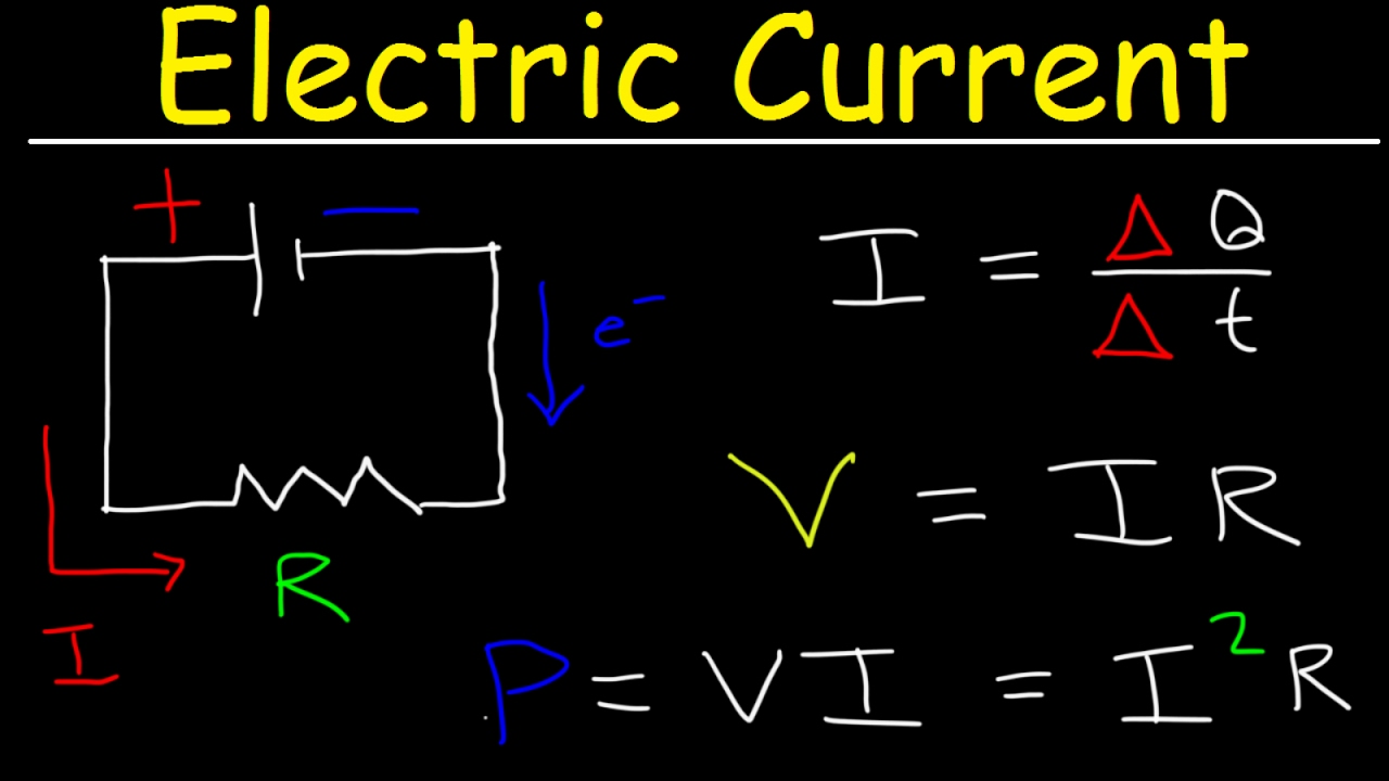
- π§ Current is represented by I and is the flow of electric charge, measured in amperes (A) or coulombs per second.
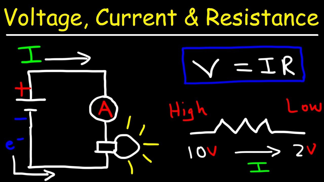
- π‘ Resistance, denoted by R, is what impedes the flow of charge in a circuit and is measured in ohms.
- π The water flow metaphor helps to understand the relationship between voltage, current, and resistance in an electric circuit.
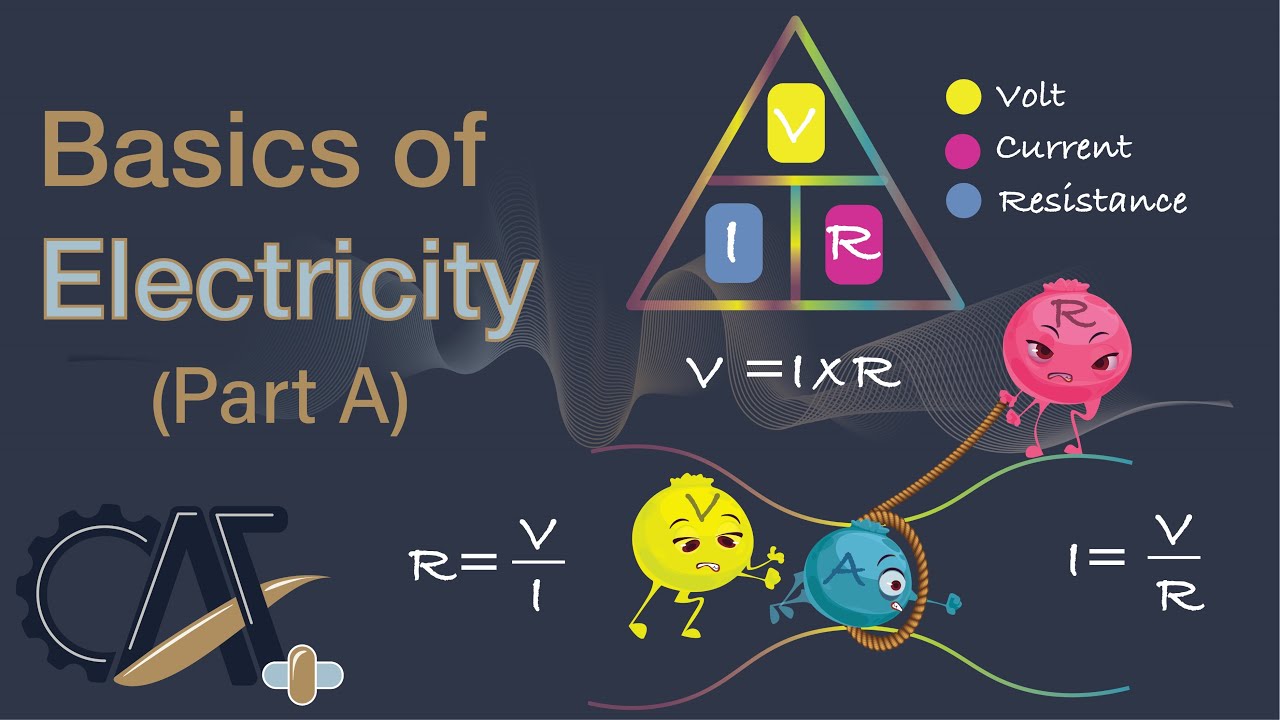
- π Ohm's law formula is V = I * R, where V is voltage, I is current, and R is resistance.
- β‘ To find the current in a circuit, use the rearranged Ohm's law formula I = V / R.
- π When a circuit is open, no current flows, similar to a closed pipe preventing water flow.
- π Closing the circuit allows electrons to flow, analogous to opening a pipe and allowing water to flow.
- π The direction of conventional current is from the positive to the negative terminal, opposite to the actual flow of electrons.
- π Even in simple wires, there is some resistance, which is denoted by a jagged line in circuit diagrams.
Q & A
What is the fundamental law introduced in the video script related to electric circuits?
-The fundamental law introduced in the video script is Ohm's Law, which is the most basic law when dealing with electric circuits.
What does Ohm's Law connect in the context of circuits?
-Ohm's Law connects the concepts of voltage, current, and resistance, showing the relationship between these three electrical quantities.
What is the mathematical relationship given by Ohm's Law?
-The mathematical relationship given by Ohm's Law is that voltage (V) is equal to current (I) times resistance (R), or rearranged, current (I) is equal to voltage (V) divided by resistance (R).
What is the symbol used to denote current in the script?
-The symbol used to denote current in the script is the capital letter 'I'.
What is the intuitive explanation for voltage in the script?
-Voltage is intuitively explained as electric potential energy, specifically potential energy per unit charge, with the units being volts.
How is current analogous to the flow of water in the provided metaphor?
-In the water flow metaphor, current is analogous to the amount of water flowing through a pipe per unit of time, measured in coulombs per second.
What is the role of resistance in the context of the water flow metaphor?
-In the water flow metaphor, resistance is analogous to a narrowing of the pipe, which impedes the flow of water, similar to how resistance impedes the flow of electric charge in a circuit.
What is the unit of resistance and how is it denoted?
-The unit of resistance is the ohm, denoted with the Greek letter omega (Ξ©).
How is the direction of current flow determined in electric circuits, according to the script?
-The direction of current flow is determined by the convention set by Benjamin Franklin, which is from the positive to the negative terminal, despite this being opposite to the actual flow of electrons.
What is the relationship between the amount of water flowing through different parts of the pipe in the water flow metaphor?
-In the water flow metaphor, the amount of water flowing through different parts of the pipe in a second must be the same due to the continuity of flow, similar to the current being the same at different points in an electric circuit.
How is the current in the example circuit calculated using Ohm's Law?
-The current in the example circuit is calculated using Ohm's Law by dividing the voltage (16 volts) by the resistance (8 ohms), resulting in a current of 2 amperes.
Outlines
π Introduction to Electric Circuits and Ohm's Law
This paragraph introduces the fundamental concepts of electric circuits, focusing on Ohm's law as the cornerstone of circuit analysis. It explains the basic elements of voltage, current, and resistance, using the analogy of water flow to build an intuitive understanding. Voltage is likened to electric potential energy per unit charge, measured in volts, while current represents the flow of charge over time, measured in amperes or coulombs per second. Resistance is portrayed as a factor that impedes the flow, similar to a narrowing in a water pipe, and is measured in ohms. The relationship between these elements is encapsulated in Ohm's law, expressed as voltage equals current times resistance, or alternatively, current equals voltage divided by resistance.
π Applying Ohm's Law to a Simple Electric Circuit
Building upon the foundational concepts introduced in the previous paragraph, this section delves into applying Ohm's law to a practical example of an electric circuit. It describes constructing a circuit with a battery, illustrating the voltage across the battery terminals and the concept of an open circuit. The paragraph continues by introducing resistance into the circuit, denoted by a jagged line in a schematic diagram. A specific example is given where a 16-volt battery is connected to an 8-ohm resistor, and the listener is encouraged to calculate the resulting current using Ohm's law. The correct calculation is then revealed, showing that the current is 2 amperes. The paragraph also touches on the historical convention of current direction, which is opposite to the actual flow of electrons, a quirk stemming from early studies of electricity by Benjamin Franklin.
Mindmap
Keywords
π‘Electric Circuits
π‘Ohm's Law
π‘Voltage
π‘Current
π‘Resistance
π‘Potential Energy
π‘Kinetic Energy
π‘Coulomb
π‘Water Metaphor
π‘Battery
π‘Direction of Current
Highlights
Introduction of electric circuits and Ohm's law as the fundamental concept in circuit studies.
Ohm's law formula: Voltage equals current times resistance, and its rearranged form to find current.
Explanation of voltage as electric potential energy per unit charge, measured in volts.
Current defined as the flow of electric charge per unit time, measured in amperes.
Resistance as a factor that impedes the flow of electric charge, symbolized by R and measured in ohms.
Use of a water flow metaphor to explain the relationship between voltage, current, and resistance.
Potential energy in water flow is analogous to voltage, demonstrating the conversion to kinetic energy.
Current in water flow is compared to the rate of water passing a point in the pipe per unit time.
Resistance in the water flow metaphor is represented by a narrowing of the pipe, impeding water flow.
Building an electric circuit with a battery, illustrating voltage across the battery terminals.
Practical representation of resistance in a circuit diagram with a jagged line.
Calculation of current in a circuit using Ohm's law with given voltage and resistance values.
Direction of current flow in circuits, the historical convention, and its relation to electron flow.
Current measurement consistency across different points in a simple circuit due to resistance.
The quirk of current direction based on Benjamin Franklin's early studies without knowledge of electrons.
Current direction convention from positive to negative, despite being opposite to electron flow.
Practical implications of Ohm's law in understanding and calculating electric current in circuits.
Transcripts
- [Instructor] What we will introduce ourselves to
in this video is the notion of electric circuits
and Ohm's law, which you can view
as the most fundamental law
or the most basic law or simplest law
when we are dealing with circuits.
And it connects the ideas of voltage,
which we will get more of a intuitive idea for
in a second, and current,
which is denoted by capital letter I,
I guess to avoid confusion if they used a capital C
with the coulomb.
And what connects these two is the notion of resistance.
Resistance,
that is denoted with the capital letter R.
And just to cut to the chase,
the relationship between these
is a pretty simple mathematical one.
It is that voltage is equal to current
times resistance or another way to view it,
if you divide both sides by resistance,
you get that current is equal to voltage
divided by resistance.
Voltage divided by resistance.
But intuitively, what is voltage?
What is current?
And what is resistance?
And what are the units for them
so that we can make sense of this?
So to get an intuition for what these things are
and how they relate, let's build a metaphor using
the flow of water, which isn't a perfect metaphor,
but it helps me at least understand the relationship
between voltage, current, and resistance.
So let's say I have this vertical pipe of water,
it's closed at the bottom right now,
and it's all full of water.
There's water above here as well.
So the water in the pipe,
so let's say the water right over here,
it's gonna have some potential energy.
And this potential energy, as we will see,
it is analogous to voltage.
Voltage is electric potential, electric potential.
Now it isn't straight up potential energy,
it's actually potential energy per unit charge.
So let me write that.
Potential energy per unit,
unit charge.
You could think of it as joules, which is potential energy,
or units of energy per coulomb.
That is our unit charge.
And the units for voltage in general is volts.
Now, let's think about what would happen
if we now open the bottom of this pipe.
So we open this up.
What's gonna happen?
Well, the water's immediately gonna drop straight down.
That potential energy is gonna be converted
to kinetic energy.
And you could look at a certain part of the pipe
right over here, right over here.
And you could say, well,
how much water is flowing per unit time?
And that amount of water that is flowing
through the pipe at that point
in a specific amount of time,
that is analogous to current.
Current is the amount of charge,
so we could say charge per unit time.
Q for charge,
and t for time.
And intuitively you could say,
how much, how much charge
flowing,
flowing past
a point in a circuit, a point in
circuit
in a, let's say, unit of time,
we could think of it as a second.
And so you could also think about it as coulombs per second,
charge per unit time.
And the idea of resistance is something could just keep
that charge from flowing at an arbitrarily high rate.
And if we want to go back to our water metaphor,
what we could do is, we could introduce something
that would impede the water,
and that could be a narrowing of the pipe.
And that narrowing of the pipe
would be analogous to resistance.
So in this situation, once again,
I have my vertical water pipe,
I have opened it up,
and you still would have that potential energy,
which is analogous to voltage,
and it would be converted to kinetic energy,
and you would have a flow of water through that pipe,
but now at every point in this pipe,
the amount of water that's flowing past
at a given moment of time is gonna be lower,
because you have literally this bottleneck right over here.
So this narrowing is analogous to resistance.
How
much
charge
flow
impeded,
impeded.
And the unit here is the ohm,
is the ohm,
which is denoted with the Greek letter omega.
So now that we've defined these things
and we have our metaphor,
let's actually look at an electric circuit.
So first, let me construct a battery.
So this is my battery.
And the convention is my negative terminal
is the shorter line here.
So I could say that's the negative terminal,
that is the positive terminal.
Associated with that battery,
I could have some voltage.
And just to make this tangible,
let's say the voltage
is equal to 16 volts across this battery.
And so one way to think about it is
the potential energy per unit charge,
let's say we have electrons here
at the negative terminal,
the potential energy per coulomb here is 16 volts.
These electrons, if they have a path,
would go to the positive terminal.
And so we can provide a path.
Let me draw it like this.
At first, I'm gonna not make the path available
to the electrons, I'm gonna have an open circuit here.
I'm gonna make this path
for the electrons.
And so as long as our circuit is open like this,
this is actually analogous to the closed pipe.
The electrons, there is no way for them to get
to the positive terminal.
But if we were to close the circuit right over here,
if we were to close it, then all of a sudden,
the electrons could begin to flow through this circuit
in an analogous way to the way
that the water would flow down this pipe.
Now when you see a schematic diagram like this,
when you just see these lines,
those usually denote something that has no resistance.
But that's very theoretical.
In practice, even a very simple wire that's a good conductor
would have some resistance.
And the way that we denote resistance is with a jagged line.
And so let me draw resistance here.
So that is how we denote it in a circuit diagram.
Now let's say the resistance here is eight ohms.
So my question to you is,
given the voltage and given the resistance,
what will be the current through this circuit?
What is the rate at which charge will flow past
a point in this circuit?
Pause this video and try to figure it out.
Well, to answer that question,
you just have to go to Ohm's law.
We wanna solve for current, we know the voltage,
we know the resistance.
So the current in this example is going to be our voltage
which is 16 volts, divided by our resistance
which is eight ohms.
And so this is going to be 16 divided
by eight is equal to two
and the units for our current,
which is charge per unit time, coulombs per second,
you could say two coulombs per second,
or you could say amperes.
And we can denote amperes with a capital A.
We talked about these electrons flowing,
and you're gonna have two coulombs worth
of electrons flowing per second
past any point on this circuit.
And it's true at any point,
same reason that we saw over here.
Even though it's wider up here and it's narrower here,
because of this bottleneck, the same amount of water
that flows through this part of the pipe in a second
would have to be the same amount that flows through
that part of the pipe in a second.
And that's why for this circuit,
for this very simple circuit,
the current that you would measure at that point,
this point, and this point, would all be the same.
But there is a quirk.
Pause this video and think about what do you think
would be the direction for the current?
Well, if you knew about electrons
and what was going on,
you would say, well, the electrons are flowing
in this direction.
And so for this electric current,
I would say that it was flowing in,
I would denote the current going like that.
Well, it turns out that the convention we use
is the opposite of that.
And that's really a historical quirk.
When Benjamin Franklin was first studying circuits,
he did not know about electrons.
They would be discovered roughly 150 years later.
He just knew that what he was labeling as charge,
and he arbitrarily labeled positive and negative,
he just knew they were opposites,
he knew something like charge was flowing.
And so, in his studies of electricity,
he denoted current as going
from the positive to the negative terminal.
And so we still use that convention today,
even though that is the opposite of the direction
of the flow of electrons.
And as we will see later on,
current doesn't always involve electrons.
And so this current here is going to be
a two ampere current.
Browse More Related Video
Electric Current & Circuits Explained, Ohm's Law, Charge, Power, Physics Problems, Basic Electricity
Electric Current: Crash Course Physics #28
Ohms Law Explained | Practice Problems
Chapter 2 - Fundamentals of Electric Circuits
Electricity | Grade 8 Science DepEd MELC Quarter 1 Module 5 Part 1 Voltage, Current, Resistance
Ohmβs Law Tutorial with easy practice problems | Basic Circuits
5.0 / 5 (0 votes)