Watch How Capacitors Placement Makes a Big Difference #HighlightsRF
Summary
TLDRIn this educational video, the presenter demonstrates the importance of decoupling capacitors in electrical circuits. They start by using the largest possible capacitor to minimize noise and inductance, explaining the process of placing it close to the power source. The script explores the impact of inductance on noise levels and the significance of capacitor type, comparing a large 1000 microfarad capacitor with a smaller 1 microfarad one. The presenter concludes by showing that a smaller capacitor can actually increase noise due to its lower capacitance during high-frequency switching events, emphasizing the need for the right balance in circuit design.
Takeaways
- 🔌 The speaker emphasizes the importance of using the largest possible decoupling capacitor to reduce noise in electrical circuits.
- 🔍 They demonstrate the process of selecting and placing a 1000 microfarad capacitor close to the IC to minimize inductance and noise.
- 🚫 The script mentions the negative impact of reverse biasing the capacitor, indicating the need for correct polarity placement.
- 🔄 The speaker explains the concept of 'didt' (change in current over time) and how it relates to the flow of current through the capacitor and not through the inductance of the circuit.
- 🌐 The script discusses the role of the inner track as a ground reference, which is crucial for the correct placement of the capacitor.
- 📐 The speaker highlights the significance of minimizing inductance by reducing the distance between the capacitor and the IC, which helps in decoupling the circuit from noise.
- 🔬 An experiment is conducted to show the effect of moving the capacitor farther away, which results in increased noise due to increased inductance.
- 🔋 The script contrasts the use of electrolytic capacitors with ceramic ones, noting that the former has more inductance and is not ideal for decoupling.
- 📉 The speaker illustrates that the effectiveness of a decoupling capacitor is not solely based on its capacitance value but also on its ability to quickly respond to changes in current ('fast' capacitors).
- 🔄 The script shows that moving the capacitor closer to the IC reduces the inductance in the power rail, effectively acting as a local power supply and improving noise reduction.
- 🔧 The speaker concludes by demonstrating the impact of using a smaller 1 microfarad capacitor, which paradoxically increases noise due to its slower response to current changes.
Q & A
What is the purpose of a decoupling capacitor in an electronic circuit?
-A decoupling capacitor is used to provide local energy storage to the circuit, reducing the effects of noise and voltage fluctuations caused by switching elements. It helps to stabilize the power supply and filter out high-frequency noise.
Why is it important to place the decoupling capacitor close to the IC in the script?
-Placing the decoupling capacitor close to the IC minimizes the inductance in the power path, which can cause voltage drops and noise. This proximity ensures that the capacitor can effectively decouple the IC from the rest of the power rail inductance.
What does the script suggest about the size of the decoupling capacitor?
-The script suggests that using the biggest capacitor available might not always be the best approach. The effectiveness of a decoupling capacitor is not solely determined by its size but also by its inductance and the specific requirements of the circuit.
What is the effect of inductance on the performance of a decoupling capacitor?
-Inductance can significantly affect the performance of a decoupling capacitor by introducing additional resistance to the flow of current, especially during high-frequency switching events. Lower inductance allows the capacitor to respond more quickly and effectively to voltage changes.
Why is polarity important when connecting a decoupling capacitor?
-Polarity is crucial to avoid reverse biasing the capacitor, which could damage it or cause it to fail. The script mentions placing the negative terminal on the inside track, which is grounded, to ensure correct polarity.
What happens when the decoupling capacitor is moved farther away from the IC in the script?
-When the decoupling capacitor is moved farther away, the inductance in the power path increases, leading to more noise and voltage fluctuations. This reduces the effectiveness of the capacitor in stabilizing the power supply.
What is the significance of the waveform comparison in the script?
-The waveform comparison is used to visually demonstrate the impact of the decoupling capacitor's position and size on the power supply's stability. It allows for a direct observation of the noise levels and voltage fluctuations under different conditions.
Why might a smaller capacitor introduce more noise than a larger one in certain scenarios?
-A smaller capacitor may introduce more noise if it cannot provide sufficient energy storage for the circuit's needs during high-frequency switching. The script suggests that beyond a certain capacitance value, further increasing the size may not yield significant benefits.
What type of capacitor is recommended for use as a decoupling capacitor in the script?
-The script recommends using ceramic capacitors for decoupling purposes due to their lower inductance compared to electrolytic capacitors, making them more suitable for high-frequency applications.
What experiment is conducted in the script to demonstrate the impact of the decoupling capacitor's size?
-The experiment involves replacing a 1000 microfarad capacitor with a 1 microfarad capacitor and observing the effect on the switching noise. The script suggests that the smaller capacitor may actually increase noise due to its limited energy storage capacity.
How does the script illustrate the concept of a local power supply provided by a decoupling capacitor?
-The script explains that by placing a decoupling capacitor close to the IC, it acts as a local power supply, reducing the impact of inductance and noise from the rest of the power rail. This is why it is referred to as 'decoupling' the circuit.
Outlines

This section is available to paid users only. Please upgrade to access this part.
Upgrade NowMindmap

This section is available to paid users only. Please upgrade to access this part.
Upgrade NowKeywords

This section is available to paid users only. Please upgrade to access this part.
Upgrade NowHighlights

This section is available to paid users only. Please upgrade to access this part.
Upgrade NowTranscripts

This section is available to paid users only. Please upgrade to access this part.
Upgrade NowBrowse More Related Video
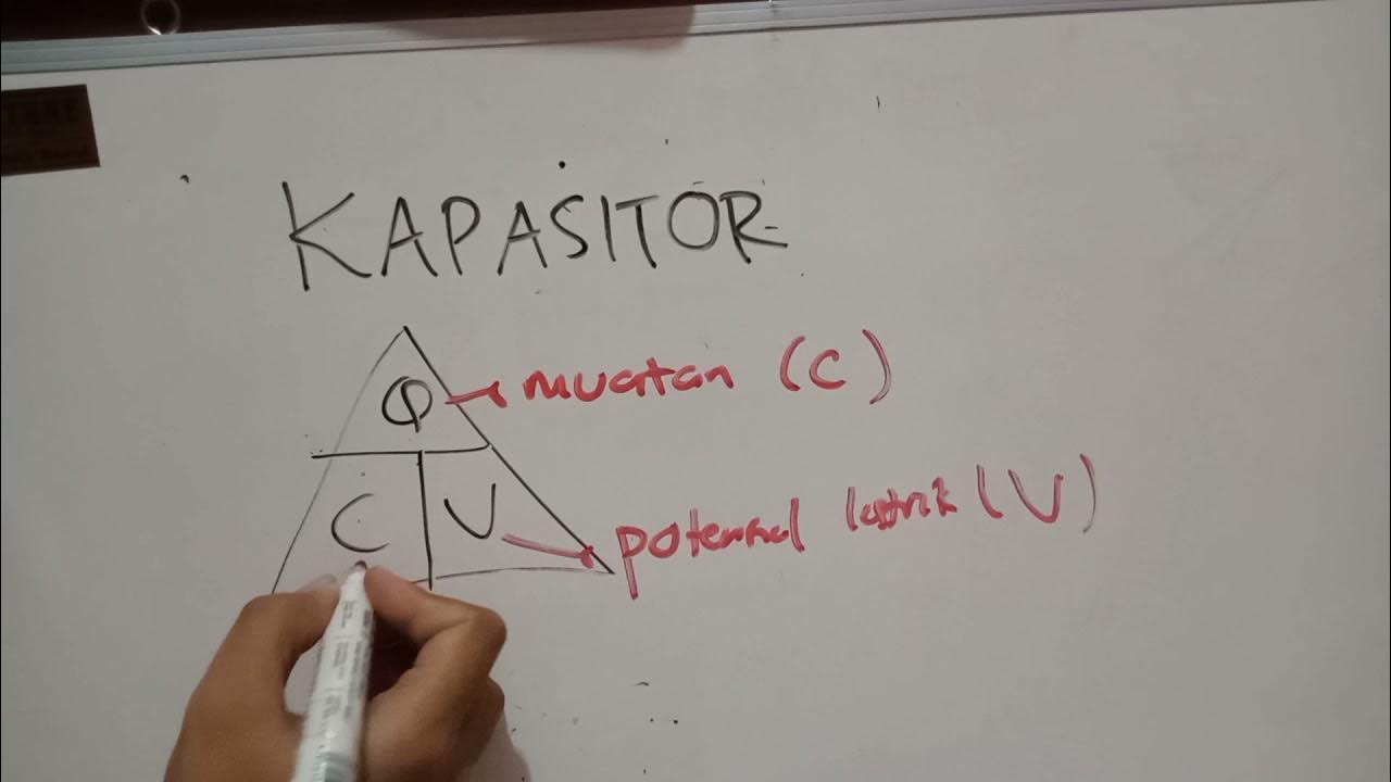
Kapasitor, Simulasi Phet, Fisika kelas XII
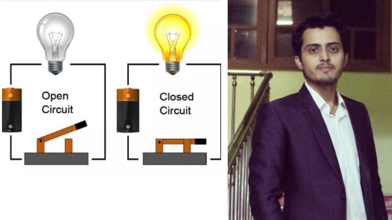
Open circuit | closed circuit | Short circuit | Easiest way to understand

The Basics of Electrical Components || Program Studi Teknik Elektro - MK : Bahasa Inggris

Elektronika Dasar 006 Capasitor 02 Universitas Jember
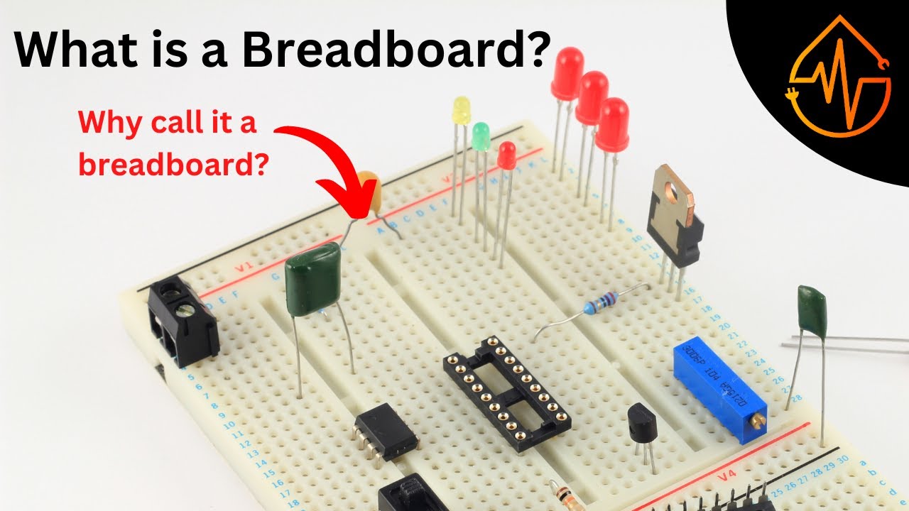
Breadboard - Explained in Depth

Electrical Engineering: Ch 8: RC & RL Circuits (1 of 43) RC & RL Circuits Introduction
5.0 / 5 (0 votes)