Class Diagram
Summary
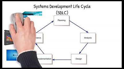
TLDRThis lecture focuses on advanced object-based software design, specifically the analysis and design phases of the SDLC. The instructor emphasizes the importance of use-case diagrams during the needs analysis phase, followed by the creation of class diagrams at the design stage. Students learn about defining classes, attributes, methods, and understanding relationships such as cardinality. The session also touches on modifiers like `public` and `private` and how to translate these designs into coding structures. The goal is to ensure that the design is implemented correctly in the software development process, aligning with the conceptual structure created during analysis.
Takeaways
- 😀 The course focuses on object-based software design, ensuring that the design aligns with the final implementation of the software.
- 😀 The **needs analysis** phase identifies functional and non-functional requirements, which are visualized using **use-case diagrams**.
- 😀 **Use-case diagrams** represent interactions between actors (e.g., students, lecturers) and the system, focusing on functional requirements.
- 😀 In the **design phase**, technical diagrams like **class diagrams** are created, which focus on the structure and behavior of the software system.
- 😀 The **class diagram** explains the structure of the system by representing classes, attributes, and methods, which will later be implemented in code.
- 😀 **Class attributes** are the properties of a class (e.g., name, date of birth, position for the Lecturer class).
- 😀 **Methods** are the functions or operations that can be performed on or by the objects of a class (e.g., a lecturer can grade assignments).
- 😀 **Modifiers** (public, private) define the visibility and accessibility of class attributes and methods in object-oriented programming.
- 😀 The **relationship between classes** (e.g., students take courses, lecturers teach courses) is illustrated in class diagrams, often using **cardinality** to define the type of relationship.
- 😀 The design phase translates functional requirements into technical specifications, helping programmers understand what to implement based on diagrams like use-case and class diagrams.
- 😀 **Cardinality** in class diagrams defines the relationships between objects, such as one-to-many or many-to-one relationships between students, lecturers, and courses.
Q & A
What is the primary focus of the course discussed in the transcript?
-The primary focus of the course is on object-based software design, ensuring that the design results align with later implementation.
What are the three main parts covered in the course?
-The course covers three main parts: needs analysis, design, and implementation.
What is the purpose of a use case diagram in object-based software design?
-A use case diagram represents the functional needs of the system by illustrating the interactions between actors (e.g., students, lecturers) and the system.
What diagrams are typically created during the design phase?
-During the design phase, at least three diagrams are created: the ER diagram, class diagram, and sequence diagram.
How is the class diagram different from the use case diagram?
-The class diagram defines the objects (classes), their attributes, and methods, while the use case diagram focuses on the interactions between actors and the system at a functional level.
What are the key components of a class diagram?
-The key components of a class diagram are the class name, attributes (variables), and methods (functions). The relationships between classes are also a critical part of the diagram.
What is the role of access modifiers in a class diagram?
-Access modifiers (e.g., public, private) define the visibility and accessibility of class attributes and methods. Public members are accessible outside the class, while private members are restricted to within the class.
Can you explain what cardinality means in a class diagram?
-Cardinality defines the number of instances of one class that can be associated with another class. It specifies relationships such as one-to-one, one-to-many, or many-to-many.
How does the implementation of a class diagram align with coding?
-When coding, the class diagram serves as a blueprint, guiding the implementation of classes, their attributes, methods, and relationships in the code. The design should match the structure outlined in the diagram.
What are the differences between the class diagram and the ER diagram?
-The ER diagram focuses on the database structure and data relationships, while the class diagram defines the structure of the classes, including their attributes and methods, and how they interact in the software system.
Outlines

This section is available to paid users only. Please upgrade to access this part.
Upgrade NowMindmap

This section is available to paid users only. Please upgrade to access this part.
Upgrade NowKeywords

This section is available to paid users only. Please upgrade to access this part.
Upgrade NowHighlights

This section is available to paid users only. Please upgrade to access this part.
Upgrade NowTranscripts

This section is available to paid users only. Please upgrade to access this part.
Upgrade NowBrowse More Related Video

27. OCR A Level (H046-H446) SLR6 - 1.2 Development methodologies part 1

Software Development Lifecycle in 9 minutes!

Software Testing Tutorial #6 - Software Development Life Cycle (SDLC)

Chapter 1: The Systems Development Environment

Pengenalan Analisis dan Desain Sistem

What is an Algorithm? - Programming Tutorial for Beginners [Algorithm Basics] - KnowledgeHut
5.0 / 5 (0 votes)