Struktur Kayu Vid06 Perencanaan Batang Tarik Part3
Summary
TLDRThis video provides a comprehensive explanation on designing wooden structural elements for a building, focusing on calculating the dimensions of tension members in a timber frame. It covers key topics such as load-bearing calculations, wood quality standards, and the use of specific design factors. The speaker walks through the process of determining the strength and dimensions of timber beams, factoring in material properties, environmental conditions, and safety considerations. The final design recommendation is a 5x10 cm timber member, with all calculations and standards thoroughly explained.
Takeaways
- 😀 The script discusses the design of a wooden structural element, focusing on the determination of required dimensions for a timber truss or beam under specific loading conditions.
- 😀 The design is based on a simple truss structure supported at points A and C, with loads applied at the joints (25 kN at each joint).
- 😀 The speaker emphasizes the importance of using standard factory dimensions for timber beams and mentions that the wood is classified as grade A, with a design value of 17.4 MPa.
- 😀 Factors such as elasticity modulus (20,000 MPa) and correction factors for various conditions like humidity are considered in the design process.
- 😀 The timber beam is required to withstand tensile forces, and various correction factors (like CM and CF) are applied to account for different conditions, with most of them set to 1 for simplification.
- 😀 The speaker mentions the importance of checking for balance between calculated forces and the available tensile strength in the timber material to ensure safety and proper performance.
- 😀 To determine the dimensions, the calculation includes a correction for factors such as wood strength (14.4 MPa after corrections) and the required cross-sectional area to bear the applied load.
- 😀 The net cross-sectional area (PU) is calculated and compared to determine if it meets the necessary requirements for strength, with a threshold value of 45,000 N for safety.
- 😀 A correction factor of 25% is added to the cross-sectional area to account for potential variations in manufacturing and real-world conditions, resulting in a final gross cross-sectional area of 3,898 mm².
- 😀 Based on the results, the calculated dimensions of 50 mm by 100 mm for the timber beam are sufficient to support the required load, confirming that the design meets the structural needs.
Q & A
What is the main focus of the script?
-The script discusses the design of a timber tie rod in a truss system, focusing on calculations related to tensile stress, material properties, and dimensional specifications for timber components.
What type of wood is used in the design, and what is its grade?
-The wood used is classified as Grade A timber with a strength code of E20, which is referenced from design tables for material properties.
What is the significance of the 25 KN load mentioned in the script?
-The 25 KN load is applied to each node in the truss structure and is used to calculate the forces acting on the timber components. It is crucial for determining the strength and dimensions of the timber tie rod.
What does the factor '1.4T' represent in the script?
-The factor '1.4T' represents the load combination used in the design, accounting for both dead and live loads. This factor helps scale the load applied during the calculations.
How are the material properties of the timber determined?
-The material properties, such as the allowable strength (Fb) and modulus of elasticity (E), are obtained from design tables specific to the E20 timber grade, with adjustments for environmental conditions like dry air.
What role does the correction factor 'Cm' play in the design process?
-The correction factor 'Cm' adjusts the strength properties of the timber, accounting for variations such as timber orientation and specific design conditions. In this case, 'Cm' is 1 for tensile components.
Why is the tensile strength of the timber corrected in the script?
-The tensile strength is corrected by multiplying it with various factors, such as 'Cm' and other safety factors, to ensure the design is conservative and accounts for real-world variations in material properties.
How is the required cross-sectional area for the timber tie rod calculated?
-The required cross-sectional area is calculated by dividing the applied load by the corrected tensile strength. The result is then compared to the net and gross cross-sectional areas, considering a 25% safety factor for manufacturing tolerances.
What is the significance of the 1.25 factor in the cross-sectional area calculation?
-The 1.25 factor is applied to account for additional safety and manufacturing considerations, scaling the net cross-sectional area to a gross area that includes these allowances.
What is the final recommended cross-sectional dimension for the timber tie rod?
-The final recommended cross-sectional dimension for the timber tie rod is 50 mm by 100 mm, which meets the strength requirements and satisfies the safety checks outlined in the design process.
Outlines

This section is available to paid users only. Please upgrade to access this part.
Upgrade NowMindmap

This section is available to paid users only. Please upgrade to access this part.
Upgrade NowKeywords

This section is available to paid users only. Please upgrade to access this part.
Upgrade NowHighlights

This section is available to paid users only. Please upgrade to access this part.
Upgrade NowTranscripts

This section is available to paid users only. Please upgrade to access this part.
Upgrade NowBrowse More Related Video
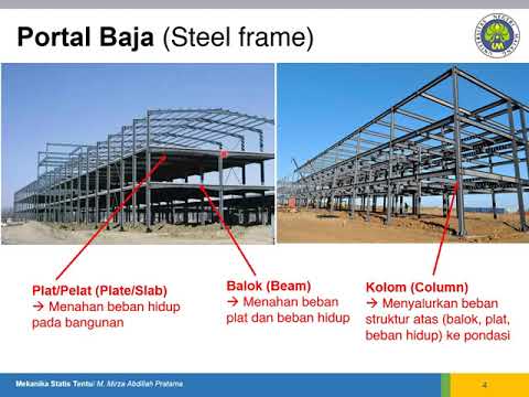
Mekanika Statis Tentu: Struktur dan Elemen Bangunan
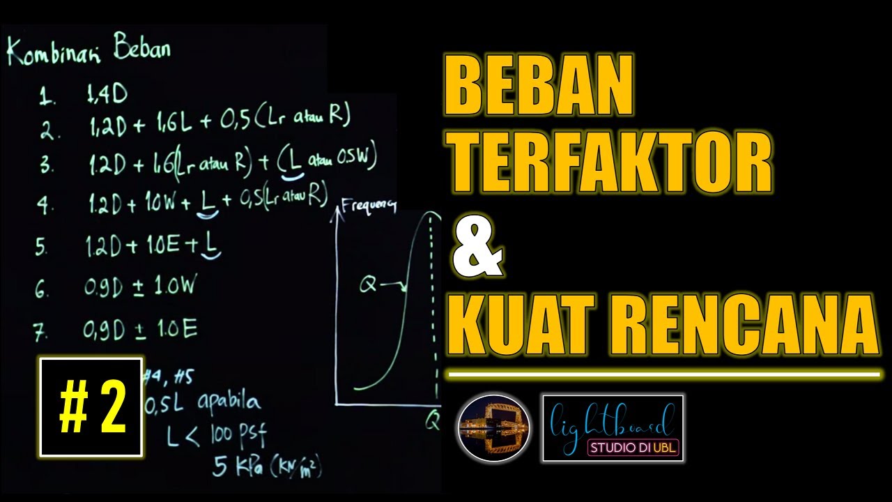
Beban Terfaktor (Ultimate Load) dan Kuat Rencana (Design Strength) Struktur Baja | Lightboard

Calculate Wall Bracing - Part 2- Determine Wind Pressure

Preliminary Design : Struktur Baja

SK04A Struktur Kayu Contoh soal Truss Part 1

Example Timber Design Compression Member by dRBI
5.0 / 5 (0 votes)