Chapter 10 - Exploring Stepper Motors (28-BYJ-48) with an Arduino
Summary
TLDREste script ofrece una introducción a cómo controlar el motor paso a paso 28BYJ-48 con Arduino, una herramienta popular para proyectos de electrónica. Se discute la estructura del motor, su alto torque a baja velocidad y su uso en aplicaciones que requieren control preciso de posición y velocidad. Se explica cómo se organizan las bobinas en fases y cómo se activan secuencialmente para mover el rotor. Se presenta un diagrama esquemático del controlador ULN2003 y cómo se conecta a Arduino. Además, se incluye un ejemplo de código para controlar el motor, así como una discusión sobre la precisión y especificaciones técnicas del motor, incluyendo su relación de reducción de engranajes y el ángulo de paso. Finalmente, se menciona la biblioteca de Arduino para steppers y se comparan las secuencias de 4 y 8 pasos, así como se habla de las placas de motor (shields) como una alternativa para controlar motores.
Takeaways
- 😀 El video es una introducción al control de motores paso a paso 28BYJ-48 con Arduino.
- 🔧 Se utiliza un motor paso a paso popular y ampliamente disponible para demostraciones.
- 📚 Se recomienda revisar capítulos 4, 5, 8 y 9 para comprender mejor este resumen.
- 🤖 Los motores paso a paso son útiles para aplicaciones que requieren posicionamiento preciso y control de velocidad.
- 🌀 Estos motores ofrecen alto torque a baja velocidad, pero tienen menos torque a alta velocidad y consumen corriente constante.
- 🪢 El motor 28BYJ-48 es unipolar, con cuatro bobinas asociadas a cables de colores que se controlan mediante un driver ULN2003.
- 🔌 El controlador ULN2003 utiliza transistores y diodos para conectar las bobinas al motor y se controla con señales de Arduino.
- 🔋 Se debe verificar la especificación de voltaje y corriente del motor para asegurarse de que Arduino pueda manejar la carga.
- 📝 Se muestra cómo conectar los pines de Arduino al controlador y un potenciómetro al pin analógico para control de velocidad.
- 🔄 Se discuten las secuencias de pulsos necesarias para mover el motor en sentido horario e antihorario.
- 🎛 El ángulo de paso del motor y la relación de reducción de engranajes son clave para la precisión en el posicionamiento del motor.
- 🔄 Se menciona la posibilidad de desalineación o 'slippage' debido a la complejidad de los engranajes internos del motor.
- 📚 Se presenta la biblioteca de Arduino para motores paso a paso, que simplifica el proceso de control del motor.
- 🛠 Se mencionan alternativas como las shields de motor que facilitan la conexión y control de motores con Arduino.
Q & A
¿Qué es un motor paso a paso y cómo funciona?
-Un motor paso a paso es un tipo de motor DC que se puede controlar para moverse en pasos discretos, lo cual es ideal para aplicaciones que requieren una posición y control de velocidad precisos. Funciona a través de múltiples bobinas organizadas en fases que, al ser electrificadas secuencialmente, hacen girar la motor en pasos sucesivos.
¿Por qué se usan motores paso a paso en lugar de otros tipos de motores?
-Los motores paso a paso son útiles debido a su alta precisión y control de posición y velocidad, además de ofrecer un alto torque en precisión a bajas velocidades, algo que no es típico en los motores DC comunes.
¿Cuáles son las desventajas de usar motores paso a paso?
-Los motores paso a paso tienen menos torque a altas velocidades, consumen corriente constante independientemente de la carga, lo que significa que no son tan eficientes, y a diferencia de los servos, no tienen un mecanismo de retroalimentación para determinar su posición.
¿Qué es el controlador de motor ULN2003 y cómo se utiliza con un motor paso a paso?
-El controlador de motor ULN2003 es un chip que contiene transistores y diodos útiles para electrificar las bobinas múltiples de un motor paso a paso. Se utiliza para controlar la dirección y velocidad de la rotación al determinar la secuencia utilizada para llevar a tierra cada una de las bobinas.
¿Cómo se conecta un motor paso a paso 28BYJ-48 a un Arduino?
-El motor 28BYJ-48 es unipolar, y sus cables naranja, rosa, amarillo y azul están asociados con cuatro bobinas diferentes. Se conecta a un Arduino utilizando el chip de controlador de motor ULN2003, donde los pines de Arduino se conectan a este chip para controlar qué bobina se electrifica.
¿Qué es la relación de reducción de engranajes y cómo afecta el motor paso a paso?
-La relación de reducción de engranajes se refiere a cómo el eje del motor gira las salidas de engranajes. En el caso del motor 28BYJ-48, una relación de 1 a 64 significa que 64 revoluciones del eje del motor giran un eje de salida completo.
¿Cuál es el ángulo de paso del motor paso a paso 28BYJ-48 y cómo se calcula?
-El ángulo de paso del motor 28BYJ-48 es de 5.625 grados por paso en una secuencia de 8 pasos, resultando en 64 pasos por revolución. Se calcula dividiendo 360 grados entre el ángulo de paso por paso.
¿Cómo se puede controlar la dirección y velocidad de un motor paso a paso con Arduino?
-La dirección y velocidad de un motor paso a paso se pueden controlar mediante la secuencia y el tiempo de los impulsos en los pines de Arduino que están conectados al controlador de motor ULN2003.
¿Qué es la biblioteca de motor paso a paso de Arduino y cómo se utiliza?
-La biblioteca de motor paso a paso de Arduino permite construir objetos de tipo 'Stepper'. Al definir estos objetos, se le indica el número de pasos necesarios para una revolución en el eje de salida del motor y los pines de Arduino que están conectados al motor. La biblioteca proporciona funciones como 'step' para inducir rotación.
¿Qué son las placas de motor y cómo facilitan el uso de motores con Arduino?
-Las placas de motor, o motor shields, son hardware que se puede adjuntar a un Arduino que maneja todos los transistores, diodos y puentes H,简化了布线工作。 Proporcionan bibliotecas personalizadas que simplifican la escritura de programas para tus proyectos.
¿Cómo se puede corregir el error de la posición del eje de salida debido al deslizamiento rotativo en un motor paso a paso?
-El deslizamiento rotativo puede introducir un error de hasta tres grados en la posición del eje de salida. Para corregir esto, se puede calibrar el código agregando pasos adicionales, como se menciona en el script, para alcanzar los ángulos deseados.
Outlines

This section is available to paid users only. Please upgrade to access this part.
Upgrade NowMindmap

This section is available to paid users only. Please upgrade to access this part.
Upgrade NowKeywords

This section is available to paid users only. Please upgrade to access this part.
Upgrade NowHighlights

This section is available to paid users only. Please upgrade to access this part.
Upgrade NowTranscripts

This section is available to paid users only. Please upgrade to access this part.
Upgrade NowBrowse More Related Video
PWM Explicado | Cómo hacer un controlador de velocidad de motores DC

Construyo un AVIÓN en Miniatura REAL que Funciona ✈️😍

ARDUINO UNO KIT ELEGOO | APRENDE ARDUINO EN 15 MINUTOS

✅ El más usado en Robótica para controlar Motores DC, Motores de Pasos, Driver L298N Puente H

ALARMA CASERA ANTIRROBO con ARDUINO y SENSOR ULTRASÓNICO | Como hacer
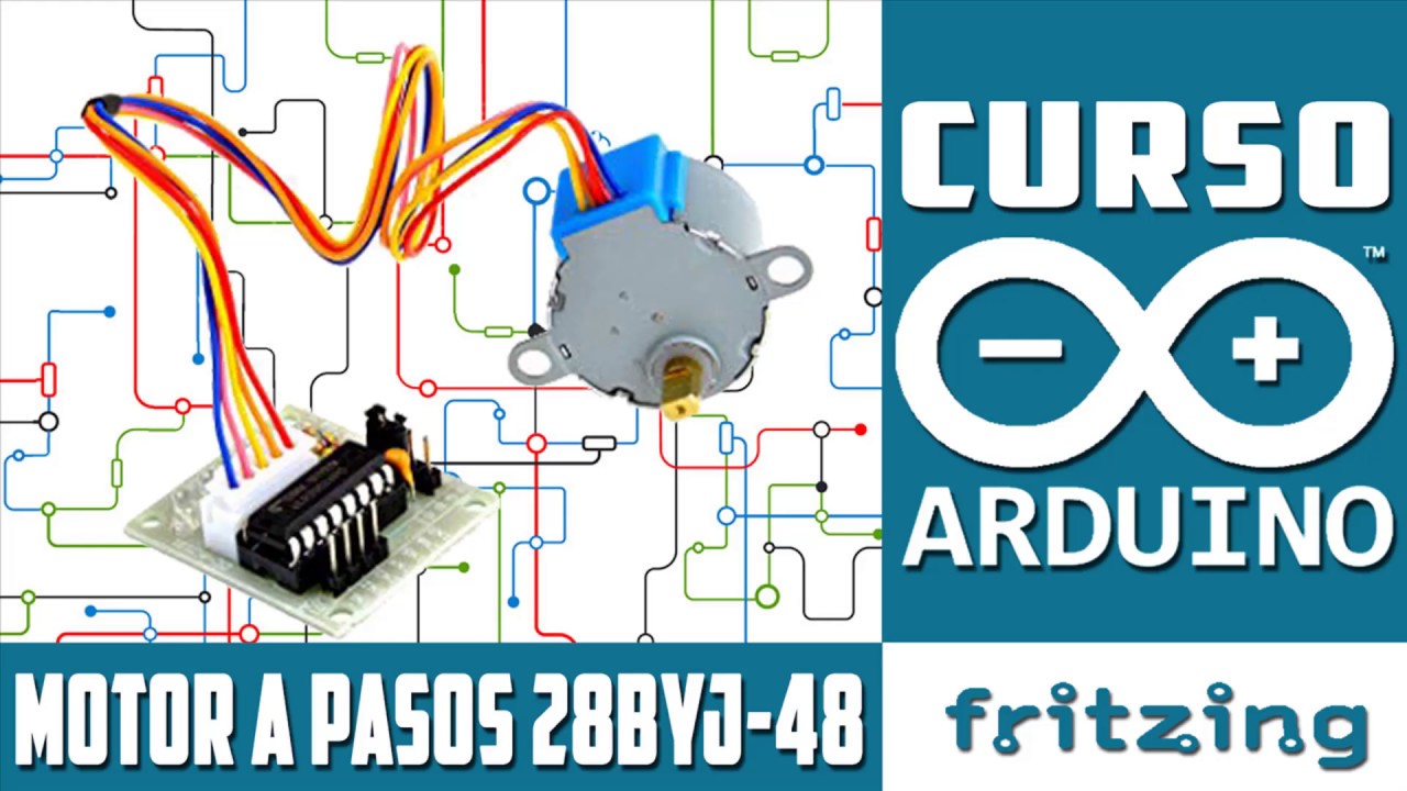
✅ Control de Motor a pasos 28BYJ-48 | Stepper - Curso Básico de Arduino UNO
5.0 / 5 (0 votes)
