Bipolar Junction Transistor

RED Inc. Communications
14 Oct 201604:07

Summary

TLDRThe video script delves into bipolar junction transistors (BJTs), highlighting their PNP or NPN semiconductor sandwich structure and their function as current regulators. It explains the three leads: emitter, base, and collector, with the emitter's arrow indicating the BJT type. BJTs can act as solid-state relays, offering advantages over mechanical switches, such as reduced arcing and shock risk. The script also covers the transistor's operation in cutoff and saturation states and its testing with a multimeter. The importance of understanding BJTs for their widespread use in electronic circuits is emphasized.

Takeaways

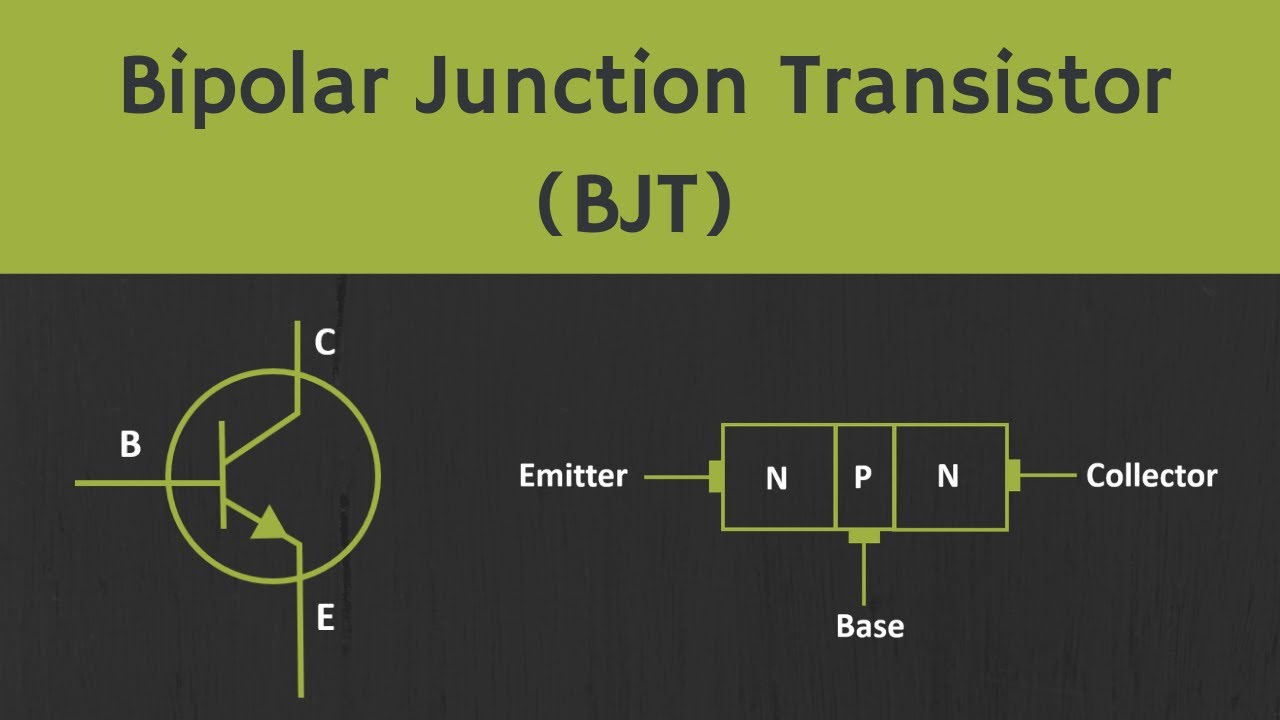
  • 🌟 Bipolar Junction Transistors (BJTs) are semiconductor devices with either a PNP or NPN structure, named for their dual semiconductor material layers.
  • 🔍 BJTs have three leads: emitter, base, and collector, with the emitter's direction indicated by an arrow on the schematic symbol.
  • 👉 The direction of the arrow in the schematic symbol helps identify the type of BJT: NPN or PNP.
  • 🚦 BJTs function as current regulators, allowing a small emitter-base current to control a larger collector-emitter current.
  • ⚡ Proper voltage biasing is essential for BJTs to operate correctly, ensuring the controlling and controlled currents flow in the right direction.
  • 🔄 BJTs can be used as switching elements, offering advantages over mechanical switches such as reduced arcing, heating, and shock risk.
  • 🛡 A transistor can act as a solid-state relay, turning on or off with a small controlling current and voltage compared to the controlled load.
  • 🔒 BJTs have a cutoff state with zero current, where they are non-conducting, and a saturation state with maximum current, where they are fully conducting.
  • 🛠 When tested with a multimeter, BJTs behave like two back-to-back PN junctions, requiring proper biasing to function.
  • 🔌 The emitter-base PN junction must be forward-biased to allow current flow, while the base-collector junction is normally reverse-biased to block current.
  • 🌐 BJTs are versatile components found in almost every electronic circuit, making understanding their operation fundamental to electronics.

Q & A

  • What is a bipolar junction transistor (BJT)?

    -A bipolar junction transistor (BJT) is a type of semiconductor device that consists of a PNP or NPN sandwich structure. It is commonly referred to as a BJT because the controlled current must go through two types of semiconductor material, p and n.

  • How are the schematic symbols for NPN and PNP BJTs different?

    -The schematic symbols for NPN and PNP BJTs differ by the direction of the arrow. The emitter lead can always be identified by the arrow, and the direction of the arrow identifies the type of BJT. An NPN arrow is not pointed in the same direction as the PNP arrow.

  • What are the three leads of a BJT called?

    -The three leads of a BJT are called the emitter, base, and collector.

  • How does a BJT function as a current regulator?

    -A BJT functions as a current regulator by allowing a small amount of emitter-base current to control a larger collector-emitter current, provided that the controlling base-emitter current and the controlled collector-emitter current are going in the proper direction.

  • What are the disadvantages of using a conventional mechanical switch for controlling DC power to a load?

    -Conventional mechanical switches have several disadvantages, including damage to the mechanical switch due to arcing, heating, and the potential risk of shock to the operator.

  • How can a transistor be used as an alternative to a mechanical switch?

    -A transistor can be used as a solid-state relay, offering an alternative to a mechanical switch. With the proper current and voltage biasing, the transistor can be turned on or off, and the controlling current and voltage are typically very small compared to the controlled current and voltage.

  • What is the state of a transistor when it has zero current through it?

    -When a transistor has zero current through it, it is said to be in a state of cutoff, meaning it is fully non-conducting or off.

  • What is the state of a transistor when it has maximum current through it?

    -When a transistor has maximum current through it, it is said to be in a state of saturation, meaning it is fully conducting or on.

  • How does a transistor behave when tested with a multimeter in resistance or diode check modes?

    -When tested with a multimeter in resistance or diode check modes, a transistor behaves like two back-to-back PN junctions, which are better known as a simple diode.

  • What is necessary for a BJT to be properly biased on or off?

    -A BJT must have proper voltage applied to bias the transistor on or off. The emitter-base PN junction must be forward biased to allow collector-emitter current to flow, and it is the potential difference between the emitter-base PN junction that turns the transistor on.

  • Why is it important to understand the emitter-base current flow in a BJT?

    -It is important to understand the emitter-base current flow in a BJT because it regulates the amount of current between the collector and emitter, even though the base-collector junction is reverse-biased and normally blocks any current from going through the transistor between emitter and collector.

Outlines

00:00

🔌 Bipolar Junction Transistors (BJT) Basics

The script introduces bipolar junction transistors (BJTs), which are semiconductor devices with either a PNP or NPN structure. They are named BJTs because they control current through two types of semiconductor materials, p and n. The script explains the schematic symbols for both npn and PNP BJTs, identifying the emitter, base, and collector leads. The emitter is marked by an arrow indicating the type of BJT. The BJT functions as a current regulator, where a small emitter-base current controls a larger collector-emitter current, provided the correct voltage biasing is applied. The script also discusses the advantages of using BJTs as solid-state relays over conventional mechanical switches, highlighting benefits such as reduced risk of damage due to arcing, heating, and shock.

Mindmap

Keywords

💡Bipolar Junction Transistors (BJTs)

Bipolar Junction Transistors, or BJTs, are semiconductor devices that can amplify or switch electronic signals and electrical power. They are a fundamental component in many electronic circuits. The script describes BJTs as having a 'PNP or NPN semiconductor sandwich structure' and being involved in controlling current flow through the use of two types of semiconductor material, p-type and n-type. The BJTs are central to the video's theme of explaining how these devices function and their applications in electronics.

💡Emitter

The emitter is one of the three leads of a BJT and plays a crucial role in the functioning of the transistor. It is identified by the arrow in the schematic symbol, which points towards it in an NPN BJT and away from it in a PNP BJT. The emitter is responsible for providing a large number of charge carriers that contribute to the current flow within the transistor. The script mentions that 'the emitter lead can always be identified by the arrow', highlighting its importance in understanding the BJT's operation.

💡Base

The base is another lead of the BJT and serves as the control element for the transistor. It is thin and lightly doped, allowing a small current to control a larger current flow between the emitter and collector. The script explains that the BJT functions as a 'current regulator by allowing a small amount of emitter base current to control a larger collector emitter current', emphasizing the base's role in regulating the transistor's operation.

💡Collector

The collector is the third lead of the BJT and is responsible for collecting the charge carriers that have passed through the base. It is designed to handle a large current, which is controlled by the base-emitter current. The script describes the BJT's function as a 'current regulator', where the collector-emitter current is controlled by the base-emitter current, showing the collector's importance in the BJT's current control mechanism.

💡NPN and PNP

NPN and PNP are the two types of BJT configurations, differentiated by the arrangement of p-type and n-type semiconductor layers. The script mentions that 'these are the schematic symbols for NPN and PNP bipolar junction transistors', indicating that the direction of the arrow in the symbol determines the type of BJT. The type is crucial for understanding the flow of current and the proper biasing of the transistor.

💡Current Regulator

A current regulator is a device that maintains a constant current level in a circuit, regardless of changes in voltage or load. The script describes the BJT as functioning 'as a current regulator by allowing a small amount of emitter base current to control a larger collector emitter current'. This highlights the BJT's ability to regulate current flow, which is a key aspect of its utility in various electronic applications.

💡Switching Elements

Switching elements are used to open or close a circuit, allowing current to flow or halting it. The script mentions that 'transistors may be used as switching elements to control DC power to a load'. This refers to the BJT's ability to act as a solid-state switch, which is an alternative to mechanical switches and offers advantages such as reduced wear and tear, no arcing, and faster operation.

💡Solid State Relay

A solid-state relay (SSR) is an electronic switch that offers advantages over electromechanical relays, such as faster operation, lower noise, and no moving parts. The script refers to a transistor being used as a 'solid state relay', which means that with the proper current and voltage biasing, the transistor can be turned on or off, controlling the flow of power to a load without the need for moving parts.

💡Cut Off

Cut off is a state in which a transistor has zero current flowing through it, meaning it is fully non-conducting or off. The script states that 'when a transistor has zero current through it, it is said to be in a state of cut off'. This is an important state in the operation of BJTs, especially when used as switches, as it represents the off condition.

💡Saturation

Saturation is the state in which a transistor has maximum current flowing through it, meaning it is fully conducting or on. The script mentions that 'when a transistor has maximum current through it, it is said to be in a state of saturation'. This state is critical for applications where the transistor needs to be fully on to allow maximum current flow.

💡Biasing

Biasing is the process of applying a specific voltage to a transistor to set its operating point. The script explains that 'the BJT must have proper voltage applied to bias the transistor on or off'. Proper biasing is essential for the BJT to function correctly, as it determines whether the transistor is in the cut off, active, or saturation region.

💡PN Junction

A PN junction is a boundary or interface between a p-type and an n-type semiconductor material. The script mentions that 'a transistor behaves like two back-to-back PN Junctions'. This is fundamental to the BJT's operation, as the emitter-base and base-collector junctions together form the two PN junctions that allow for current control and regulation.

Highlights

Bipolar Junction Transistors (BJT) consist of a PNP or NPN semiconductor sandwich structure.

BJT is named for the controlled current passing through two types of semiconductor material, P and N.

The current in a BJT consists of both electron and hole flow in different parts.

The three leads of a BJT are called the emitter, base, and collector.

The emitter lead can be identified by the arrow in the schematic symbol, which indicates the BJT type.

An NPN BJT has an arrow not pointing in the symbol, differentiating it from a PNP.

BJT functions as a current regulator, allowing a small emitter-base current to control a larger collector-emitter current.

For proper functioning, the controlling base-emitter current and the controlled collector-emitter current must flow in the correct direction.

Transistors can be used as switching elements to control DC power to a load, offering advantages over conventional mechanical switches.

A transistor-based solid-state relay provides an alternative to mechanical switches, reducing risks like arcing and shock.

When a transistor has zero current, it is in a state of cutoff, fully non-conducting or off.

In a state of saturation, a transistor has maximum current and is fully conducting or on.

A multimeter can test a transistor in resistance or diode check modes, where it behaves like two back-to-back PN junctions.

The emitter-base PN junction must be forward biased for the transistor to turn on, allowing collector-emitter current to flow.

It is the emitter-based current flow that regulates the amount of current between the collector and emitter.

The reverse-biased base-collector junction normally blocks any current from going through the transistor.

BJTs have various uses and are found in almost every electronic circuit, making understanding their operation fundamental.

Transcripts

play00:03

[Music]

play00:06

bipolar Junction transistors consist of

play00:08

either a PNP or npn semiconductor

play00:12

sandwich structure the bipolar Junction

play00:15

transistor is commonly referred to as a

play00:19

BJT a BJT is so named because the

play00:22

controlled current must go through two

play00:25

types of semiconductor material p and N

play00:29

the current consists of both electron

play00:31

and whole flow in different parts of the

play00:35

BJT these are the schematic symbols for

play00:38

npn and PNP bipolar Junction

play00:42

transistors the three leads of a BJT are

play00:45

called the emitter Bas and

play00:48

collector the emitter lead can always be

play00:51

identified by the arrow the direction of

play00:54

the arrow identifies the type of

play00:56

BJT an easy way to determine which type

play00:59

of BJT is depicted by the symbol is to

play01:02

look at the arrow remember that the

play01:04

arrow of an npn is not pointed in

play01:09

npn the BJT functions as a current

play01:12

regulator by allowing a small amount of

play01:15

emitter base current to control a larger

play01:18

collector emitter

play01:20

current in order for the BJT to properly

play01:23

function as a current regulator the

play01:25

controlling base emitter current and the

play01:28

controlled collector emitter current

play01:30

must be going in the proper direction

play01:32

this is achieved by applying the proper

play01:35

voltage

play01:36

biasing transistors may be used as

play01:39

switching elements to control DC power

play01:41

to a load in a conventional mechanical

play01:44

switch the electrical contacts move to

play01:47

open and close when the switch is

play01:49

actuated all of the circuit current

play01:52

travels through the switch there are

play01:54

many disadvantages to this type of

play01:55

circuit design some of which are the

play01:58

damage to the mechanical switch due to

play02:00

arcing Heating and the potential risk of

play02:03

shock to the

play02:04

operator a transistor can be used as a

play02:07

solid state relay and offers an

play02:09

alternative to a mechanical switch with

play02:12

the proper current and voltage biasing

play02:15

the transistor can be turned on or

play02:17

off the controlling current and voltage

play02:21

is typically very small compared to the

play02:23

controlled current and voltage this

play02:26

allows for reduced risk to the operator

play02:29

minimizing is arcing and creates many

play02:31

other control options such as a TTL

play02:35

control

play02:36

signal when a transistor has zero

play02:39

current through it it is said to be in a

play02:41

state of cut off the transistor is fully

play02:44

non-conducting or

play02:46

off when a transistor has maximum

play02:49

current through it it is said to be in a

play02:51

state of saturation the transistor is

play02:53

fully conducting or

play02:56

on tested with a multimeter in the

play02:58

resistance or diode check modes a

play03:01

transistor behaves like two back-to-back

play03:04

PN Junctions or better known as a simple

play03:08

diode the BJT must have proper voltage

play03:11

applied to bias the transistor on or off

play03:15

the emitter base PN Junction must be

play03:17

forward biased which will allow

play03:19

collector emitter current to

play03:21

flow it is the potential difference

play03:23

between the emitter base PN Junction

play03:26

that turns the transistor on however

play03:29

it's very important to note that it is

play03:31

the emitter based current flow that

play03:33

regulates the amount of current between

play03:35

the collector and

play03:36

emitter the reverse biased base

play03:39

collector Junction normally blocks any

play03:41

current from going through the

play03:43

transistor between emitter and

play03:45

collector bipolar Junction transistors

play03:48

have many different uses and are found

play03:51

in almost every electronic circuit it is

play03:53

important to understand the fundamental

play03:55

theory of operation of these

play03:58

devices

play04:01

[Music]

Rate This

5.0 / 5 (0 votes)

Related Tags
BJTsElectronicsPNPNPNCurrent RegulatorSolid StateSwitchingSemiconductorsCircuit DesignTransistor Theory