An intuitive explanation of ZVS, ZCS and pseudo ZVS
Summary
TLDRDans cette présentation, l'auteur, Saakov, explique de manière intuitive les concepts de commutation à zéro voltage (ZVS) et à zéro courant (ZCS), ainsi que la commutation à faible tension (LDO). Il illustre les notions de commutation difficile et de commutation douce, recommandant une extinction rapide et une allumage lent pour minimiser les pertes. Saakov utilise des simulations LTspice pour montrer ces concepts dans différents types de convertisseurs, y compris les convertisseurs résonants, les convertisseurs de type flyback et les convertisseurs de type LLC. Il décrit également la manière dont la commutation à zéro voltage peut être obtenue en modifiant la direction du courant à un moment critique, ce qui permet d'éviter la commutation difficile. Cette présentation est un guide utile pour comprendre les principes de base de l'efficacité énergétique dans les convertisseurs de tension.
Takeaways
- 🔌 L'explication intuitive de la commutation à zéro voltage et de la commutation à zéro courant est présentée dans la présentation.
- 📈 La commutation rapide (turn off) et l'allumage lent (turn on) sont recommandés pour minimiser les pertes d'énergie.
- 💡 La commutation à zéro voltage réduit les pertes grâce à une faible superposition entre le courant et la tension.
- 🚫 La commutation difficile (hard switching) est le pire scénario où le transistor est allumé contre un diode conducteur.
- 🔍 L'effet de l'inductance parasitaire est mentionné comme un facteur influençant la commutation.
- 🔁 La commutation à zéro voltage est obtenue grâce à une auto-commutation lorsque le courant change de direction.
- 🔄 Le mode de fonctionnement limite de courant (borderline current mode) permet d'atteindre la commutation à zéro voltage dans les convertisseurs CCM.
- 📉 En dessous de la fréquence de résonance, la commutation est difficile car le courant est toujours passant par le diode.
- ⚙️ Dans les convertisseurs résonants comme l'LLC, la fréquence de fonctionnement affecte le type de commutation (zéro voltage ou zéro courant).
- 🔽 La commutation dans les convertisseurs Flyback est influencée par la capacité de sortie et l'inductance du bobinage couplé.
- 🎯 La commutation à zéro voltage oscillante (valley zero voltage switching) nécessite un contrôleur synchronisé pour minimiser les pertes d'énergie.
Q & A
Qu'est-ce que le commutation à zéro voltage (ZVS) et comment fonctionne-t-elle?
-La commutation à zéro voltage est une technique qui permet de minimiser les pertes d'énergie dans les convertisseurs électriques en effectuant la commutation du transistor lorsque la tension est nulle. Cela se produit lorsque la courant passe par la diode et que la tension sur le transistor est déjà à zéro, ce qui réduit l'overlap entre le courant et la tension et, par conséquent, les pertes.
Quelle est la différence entre le commutation à zéro voltage et le commutation à zéro courant (ZCS)?
-Le commutation à zéro voltage (ZVS) se produit lorsque la tension est nulle pendant la commutation, tandis que le commutation à zéro courant (ZCS) se produit lorsque le courant est nul. Dans le cas de la ZCS, cela peut être observé dans les convertisseurs résonants où la fréquence est légèrement en dessous de la fréquence de résonance, ce qui signifie que le courant est toujours positif pendant la commutation.
Pourquoi est-il recommandé d'avoir une extinction rapide et une allumage lent pour les transistors dans les convertisseurs électriques?
-Une extinction rapide permet de minimiser l'overlap entre le courant et la tension, réduisant ainsi les pertes d'énergie. Un allumage lent permet de gérer le courant de manière plus contrôlée et évite les surtensions qui pourraient endommager le transistor.
Comment la commutation à zéro voltage est-elle implémentée dans les convertisseurs résonants?
-Dans les convertisseurs résonants, comme l'LLC, la commutation à zéro voltage est obtenue en opérant à une fréquence légèrement au-dessus de la fréquence de résonance. Lorsque le transistor est allumé, le courant est négatif et la diode est conductrice, ce qui permet au transistor d'être allumé à zéro voltage.
Quelle est la différence entre le fonctionnement d'un convertisseur boost et un convertisseur buck en termes de direction du courant?
-Dans un convertisseur boost, le courant sort du transistor et passe par la diode du côté bas, tandis qu'un convertisseur buck permet le courant à entrer à travers les transistors et la diode du côté haut. Cela affecte la manière dont les composants gèrent le flux de courant.
Comment l'inductance parasitaire peut-elle affecter le processus de commutation des transistors?
-L'inductance parasitaire peut causer des courants de courte durée et des surtensions lorsqu'un transistor s'allume ou s'éteint. Cela peut augmenter les pertes d'énergie et endommager les composants si non géré correctement.
Quels sont les avantages de la commutation à zéro voltage dans les convertisseurs de courant continu (CCM) et de mode de courant limité (BCM)?
-La commutation à zéro voltage dans les CCM et BCM permet de minimiser les pertes en réduisant l'overlap entre le courant et la tension. Cela peut être obtenu en changeant la direction du courant à un moment critique pour permettre au transistor d'être allumé sous zéro voltage au lieu de commutation dure.
Comment la commutation à zéro voltage est-elle affectée par la capacité de sortie du transistor dans un convertisseur de type flyback?
-Dans un convertisseur de type flyback, la capacité de sortie du transistor peut entraîner des pertes significatives lors de l'allumage du transistor, car l'énergie stockée dans la capacité est libérée soudainement, ce qui peut causer des surcourants et des pertes d'énergie. La commutation à zéro voltage peut être utilisée pour minimiser ces pertes en synchronisant l'allumage du transistor avec les oscillations de la tension de la borne de drain.
Quelle est la signification de la fréquence de résonance dans un convertisseur résonnant LLC?
-La fréquence de résonance dans un convertisseur résonnant LLC est la fréquence à laquelle les éléments inductifs et capacitifs du circuit se balancent pour créer un point de résonance. Opérer au-dessus de cette fréquence permet de réaliser la commutation à zéro voltage, tandis qu'opérer en dessous entraîne une commutation à zéro courant.
Comment la commutation à zéro voltage peut-elle être améliorée dans les convertisseurs de type flyback?
-La commutation à zéro voltage dans les convertisseurs de type flyback peut être améliorée en utilisant la commutation à zéro voltage valée (VZVS), où la tension de la borne de drain oscille après l'extinction du transistor. Un contrôleur capable de synchroniser avec ce point peut allumer le transistor à un moment où la tension est plus faible, réduisant ainsi les pertes d'énergie.
Quels sont les défis associés à l'utilisation de la commutation à zéro voltage dans les convertisseurs électriques?
-Les défis associés à l'utilisation de la commutation à zéro voltage incluent la nécessité d'un contrôleur capable de synchroniser avec les oscillations de tension et de gérer les variations de fréquence qui peuvent survenir. De plus, il faut gérer les effets de l'inductance parasitaire et de la capacité de sortie du transistor pour minimiser les pertes d'énergie.
Comment la commutation à zéro voltage peut-elle être utilisée pour améliorer l'efficacité des convertisseurs électriques?
-La commutation à zéro voltage peut être utilisée pour améliier l'efficacité des convertisseurs électriques en réduisant les pertes d'énergie lors de la commutation des transistors. Cela est particulièrement important dans les applications où la conversion de puissance est fréquente et où les pertes peuvent s'accumuler et réduire la durée de vie des composants.
Outlines

This section is available to paid users only. Please upgrade to access this part.
Upgrade NowMindmap

This section is available to paid users only. Please upgrade to access this part.
Upgrade NowKeywords

This section is available to paid users only. Please upgrade to access this part.
Upgrade NowHighlights

This section is available to paid users only. Please upgrade to access this part.
Upgrade NowTranscripts

This section is available to paid users only. Please upgrade to access this part.
Upgrade NowBrowse More Related Video

Oubliez PowerPoint : le meilleur outil IA pour des présentations top ! | Tutoriel Gamma AI

The Zero I Trust With My Life | Rifle & Pistol

Laravel Authentication Tutorial #1 - Intro & Setup
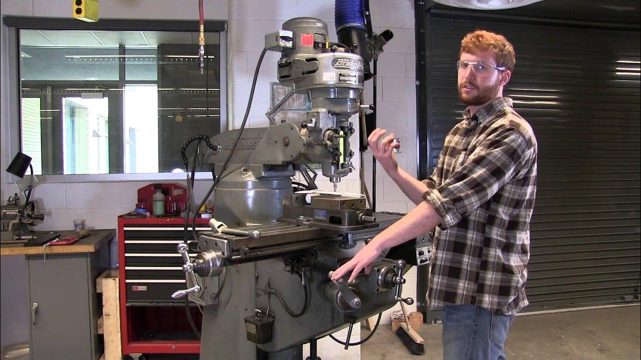
Manual Mill Tutorial

⌚🧲 Loi des boucles de courant (tension élec. , circuit en dérivation) ‖ Physique-chimie ‖ Collège
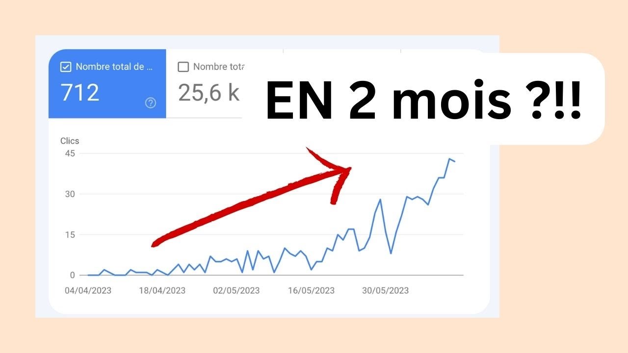
Débuter un site SEO - Quoi faire ? (étude de cas de 0 à 600 visiteurs/mois en 2 mois)
5.0 / 5 (0 votes)
