MOMENT OF INERTIA Relative to the X and Y Axes of the Beam Caixão | STATICS
Summary
TLDRIn this video, the presenter guides viewers through solving an engineering problem focused on calculating the moment of inertia for a beam's cross-sectional area. The beam consists of four wooden planks arranged as rectangles, and the presenter explains step-by-step how to apply the Parallel Axis Theorem to determine the moments of inertia about the x and y axes. Through clear explanations, viewers learn how to identify the centroids of the rectangles, apply relevant formulas, and combine results to find the total moment of inertia of the section. The video provides valuable insights for students and professionals working with structural analysis.
Takeaways
- 😀 The video explains how to calculate the moment of inertia of a beam cross-section composed of four wooden planks arranged in rectangles.
- 😀 The key geometric shapes used in the calculation are rectangles, with the moment of inertia calculated for each one individually.
- 😀 The centroid of each rectangle and the overall section are identified, which is crucial for applying the parallel axis theorem.
- 😀 The formula for the moment of inertia is presented: I = Icg + A * d², where Icg is the moment of inertia about the centroid, A is the area, and d is the distance to the axis.
- 😀 The parallel axis theorem is applied to calculate the moment of inertia relative to the specified axes (X and Y).
- 😀 The distances between the centroids of the rectangles and the axes are crucial for accurate calculations.
- 😀 Moment of inertia is calculated first for Rectangle 1, with both X and Y axes considered.
- 😀 The calculation for Rectangle 1 considers its base, height, and the distance from the centroid to the X-axis, resulting in the moment of inertia.
- 😀 A similar process is followed for Rectangle 2, including the necessary adjustments for the distances from its centroid to the axes.
- 😀 The final moment of inertia for the entire cross-section is calculated by summing the individual moments of inertia for each rectangle.
- 😀 The results of the calculations give the moment of inertia of the section with respect to both the X-axis (171.4 × 10⁶ mm⁴) and the Y-axis (462.6 × 10⁵ mm⁴).
Please replace the link and try again.
Outlines

This section is available to paid users only. Please upgrade to access this part.
Upgrade NowMindmap

This section is available to paid users only. Please upgrade to access this part.
Upgrade NowKeywords

This section is available to paid users only. Please upgrade to access this part.
Upgrade NowHighlights

This section is available to paid users only. Please upgrade to access this part.
Upgrade NowTranscripts

This section is available to paid users only. Please upgrade to access this part.
Upgrade Now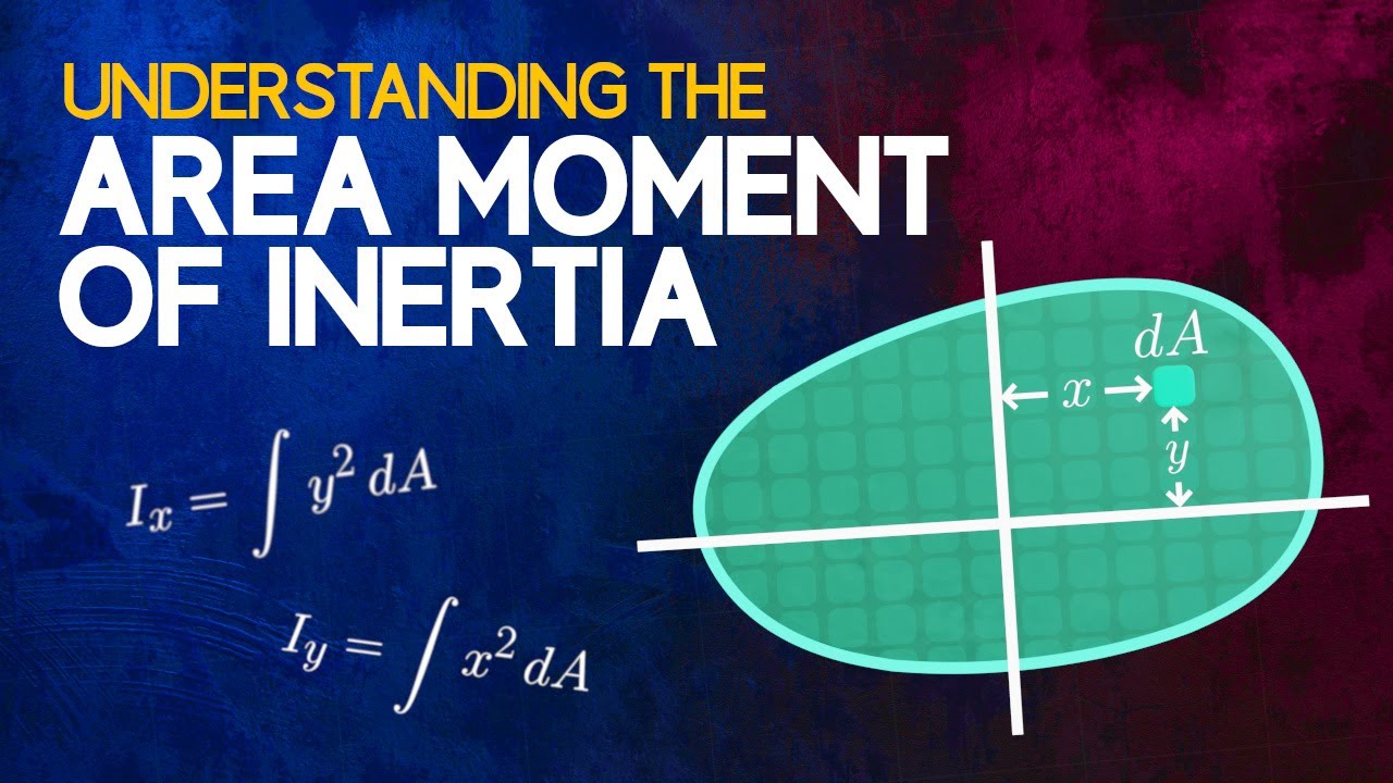


5.0 / 5 (0 votes)