How to Model a DC Motor as a System of ODEs
Summary
TLDRThis video explains how to model a DC motor using electrical and mechanical components. It begins by describing how a voltage across the motor’s terminals causes it to spin and how turning the motor induces voltage. The electrical circuit includes a voltage source, resistor, inductor, and back EMF. The mechanical side involves torque, moment of inertia, and damping. The video combines these components using Kirchhoff’s Voltage Law and mechanical torque equations to develop two key equations, which can be used to create transfer functions or state-space representations for control systems.
Takeaways
- ⚡️ The video demonstrates how to model a DC motor using electrical and mechanical equations.
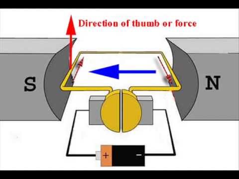
- 🔋 Applying a voltage across the motor's terminals causes it to spin, while turning the motor generates a voltage at the terminals.
- 🧲 The motor's internal coils have resistance and inductance, which are represented by a resistor and an inductor in the circuit model.
- 📐 The effect of the generated voltage when the motor turns is represented as a back electromotive force (EMF) in the circuit.
- 🔄 Kirchhoff's Voltage Law is used to derive the equation for the electrical circuit, taking into account the voltage source, resistor, inductor, and back EMF.
- ⚙️ The mechanical model of the motor includes its moment of inertia, which resists turning, and a damping factor to account for friction.
- 🔧 The mechanical torque applied to the motor is modeled with input torque, damping constant, and angular acceleration.
- 📏 Two key motor constants are defined: the torque constant (Kt) and the back EMF constant (Kb), linking electrical and mechanical equations.
- 🔗 The electrical and mechanical equations are combined using the torque and back EMF constants to form a unified model.
- 📈 The resulting equations can be used to analyze the motor using techniques like Laplace transforms or state-space representation for control problems.
Q & A
What happens when a voltage is applied across the terminals of a DC motor?
-When a voltage is applied across the terminals of a DC motor, the motor spins, converting electrical energy into mechanical energy.
What is the significance of turning the motor and measuring voltage with an oscilloscope or voltmeter?
-Turning the motor generates a voltage across the terminals, demonstrating the principle of back electromotive force (EMF), where mechanical motion induces electrical voltage.
How is the resistance of the wire inside the motor represented in the circuit model?
-The resistance of the wire is represented by a resistor labeled 'R' in the DC motor circuit model.
What role does inductance play in the DC motor model, and how is it represented?
-Inductance, due to the coiled wire in the motor, affects the circuit by resisting changes in current. It is represented by an inductor labeled 'L' in the model.
What is the function of the back EMF voltage source in the DC motor model?
-The back EMF voltage source represents the voltage generated by the motor when it spins, opposing the applied voltage and helping to regulate motor speed.
How is Kirchhoff's Voltage Law applied to the DC motor's electrical circuit?
-Kirchhoff's Voltage Law states that the sum of the voltages around a closed loop must equal zero. In the DC motor circuit, this law is used to derive an equation relating the input voltage, resistor, inductor, and back EMF.
What mechanical components are considered when modeling the motor's armature?
-The mechanical model of the armature includes the moment of inertia (J), which resists changes in rotational speed, and a damper that represents friction (B). Torque from the motor (Tm) is also applied.
What does the moment of inertia (J) represent in the mechanical model?
-The moment of inertia (J) represents the armature's resistance to changes in its rotational motion, depending on its mass and geometry.
How is torque related to the electrical and mechanical systems in the motor?
-The torque generated by the motor (Tm) is proportional to the current flowing through the circuit, with the relationship defined by the torque constant (Kt). This links the electrical system to the mechanical system.
How do the torque constant (Kt) and back EMF constant (Kb) help in linking the electrical and mechanical equations?
-The torque constant (Kt) relates the motor's torque to the current, while the back EMF constant (Kb) relates the induced voltage to the motor's angular velocity. These constants allow the electrical and mechanical systems to be connected through their shared variables.
What are the final equations that describe the DC motor's electrical and mechanical behavior?
-The electrical equation is: -V + IR + L(di/dt) + Kb(theta_dot) = 0. The mechanical equation is: KtI - B(theta_dot) = J(theta_double_dot). These equations describe the interaction between the motor's electrical input and mechanical output.
Outlines

This section is available to paid users only. Please upgrade to access this part.
Upgrade NowMindmap

This section is available to paid users only. Please upgrade to access this part.
Upgrade NowKeywords

This section is available to paid users only. Please upgrade to access this part.
Upgrade NowHighlights

This section is available to paid users only. Please upgrade to access this part.
Upgrade NowTranscripts

This section is available to paid users only. Please upgrade to access this part.
Upgrade NowBrowse More Related Video

PID control of BLDC motor
Motor VS Generator VS Alternator || How Generator, Motor And Alternator Works || In Hindi

How a DC Motor Works ? | Full Breakdown with 3D Animation
DC Motors: How Do They Work? Construction & Working Principle of a DC Motor | Electrical4U
⚡Aula15 - MOTOR CC Princípio de Funcionamento - Tensão, Torque e Potência
Cara Kerja Motor Starter Mobil Paling Gampang Dipahami
5.0 / 5 (0 votes)