SCARA Robot | How To Build Your Own Arduino Based Robot
Summary
TLDRIn this video, Dejan from HowToMechatronics.com demonstrates how to build an Arduino-based SCARA robot with 4 degrees of freedom. The robot is driven by 4 NEMA 17 stepper motors and a servo motor for the gripper. The tutorial covers designing the robot, 3D printing parts, assembling the hardware, and developing a Graphic User Interface using Processing for controlling the robot. The video also discusses forward and inverse kinematics control, with the ability to save and run automated movements.
Takeaways
- 🤖 The video tutorial guides viewers on building an Arduino-based SCARA Robot from scratch.
- 🔩 The robot features 4 degrees of freedom, driven by 4 NEMA 17 stepper motors and a servo motor for the gripper.
- 🧠 The control system consists of an Arduino UNO board, a CNC shield, and four A4988 stepper drivers.
- 🎨 A Graphic User Interface (GUI) is developed using Processing, offering both Forward and Inverse Kinematics control.
- 📏 Forward Kinematics allows manual movement of each joint to achieve a desired position, while Inverse Kinematics calculates joint angles for a given end-effector position.
- 💻 The GUI also enables saving and running stored robot movements, with adjustable speed and acceleration.
- 🖥️ The 3D model of the robot is designed using 3DEXPERIENCE Solidworks, which offers cloud-based collaboration and productivity tools.
- 🏗️ The robot's parts are primarily 3D printable, with parametric designs for easy resizing of components like GT2 pulleys.
- 🔩 Assembly involves meticulous steps including installing bearings, pulleys, motors, and wiring for each joint and the end-effector.
- 🔌 The electronics are connected using an Arduino UNO, with a case designed to house the board and maintain heat sink clearance.
- 🔩 The robot's rigidity could be improved, as the base tends to bend under stress, indicating potential areas for future design enhancements.
Q & A
What is the main focus of the video?
-The video focuses on teaching viewers how to build an Arduino-based SCARA robot, from designing to developing a Graphic User Interface for controlling it.
How many degrees of freedom does the SCARA robot have?
-The SCARA robot has 4 degrees of freedom.
What motors are used to drive the robot?
-The robot is driven by 4 NEMA 17 stepper motors and a small servo motor for controlling the end effector.
What is the brain of the SCARA robot?
-The brain of the SCARA robot is an Arduino UNO board paired with a CNC shield.
What features does the Graphic User Interface have?
-The Graphic User Interface features both Forward and Inverse Kinematics control, allowing manual movement of each robot joint or automatic calculation of joint angles for a desired end effector position.
How can the robot operate automatically?
-The robot can operate automatically by saving each movement or position using the 'Save' button and then executing the stored movements in a loop by pressing the 'Run' button.
What software was used to design the 3D model of the robot?
-The 3D model of the robot was designed using 3DEXPERIENCE Solidworks.
What is unique about the 3DEXPERIENCE Solidworks software?
-3DEXPERIENCE Solidworks is Solidworks with cloud capabilities, allowing access to data and models from anywhere in the world, and includes productivity and management apps.
What materials were used for 3D printing the robot parts?
-PLA+ material was used for most parts, while normal PLA was used for the pulleys and the gripper.
How long did it take to print all the parts for the robot?
-It took around 120 hours to print all the parts at a 60mm/s printing speed.
What electronic components are used in the project?
-The project uses an Arduino UNO board, a CNC shield, and four A4988 stepper drivers.
How is the robot controlled in terms of positioning and orientation?
-The robot is controlled using both forward and inverse kinematics, with the latter being more commonly used in robotics for positioning the end-effector to specific coordinates.
What limitations were encountered when using the AccelStepper library?
-The AccelStepper library has limitations when it comes to implementing acceleration and deceleration for smoother operation of the robot.
What issues were noted regarding the robot's rigidity?
-The robot was found to be less rigid than expected, with the Z-axis and arms supported mainly by the first joint, leading to some bending, and the belts introducing backlash.
Outlines

This section is available to paid users only. Please upgrade to access this part.
Upgrade NowMindmap

This section is available to paid users only. Please upgrade to access this part.
Upgrade NowKeywords

This section is available to paid users only. Please upgrade to access this part.
Upgrade NowHighlights

This section is available to paid users only. Please upgrade to access this part.
Upgrade NowTranscripts

This section is available to paid users only. Please upgrade to access this part.
Upgrade NowBrowse More Related Video

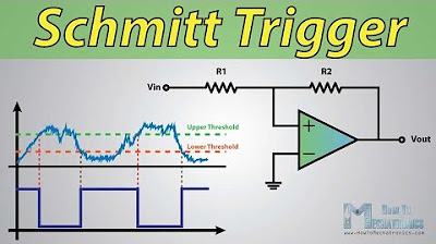
What Is Schmitt Trigger and How It Works

How a 555 Timer IC Works

How to make cardboard Cannon that shoots | DIY cardboard artillery crafts

DISPENSADOR DE ALIMENTO PARA MASCOTAS - HECHO DE MATERIAL RECICLADO - Reyna Mora

¿Por qué NO PODEMOS Alcanzar el CERO ABSOLUTO? ( Ni siquiera Camus! )

TRANSFORMA tu REALIDAD: La PROACTIVIDAD y Cómo Fomentarla
5.0 / 5 (0 votes)