Operational Amplifiers - Differential Amplifiers
Summary
TLDRIn this educational video, David Williams, an instructor at Okanogan College, explains the workings of a differential amplifier, distinguishing it from a differentiator. He assumes an ideal operational amplifier and uses the superposition principle to demonstrate how the output voltage is proportional to the difference between the two input voltages, V1 and V2. Williams simplifies the concept by showing how the output is affected by each input separately and then combines these effects to reveal the overall operation. He also discusses special cases, such as when all resistors are equal or when specific pairs of resistors are equal, and their impact on the output.
Takeaways
- ๐ David Williams, an instructor at Okanogan College, introduces the concept of differential amplifiers, emphasizing their distinction from differentiators.
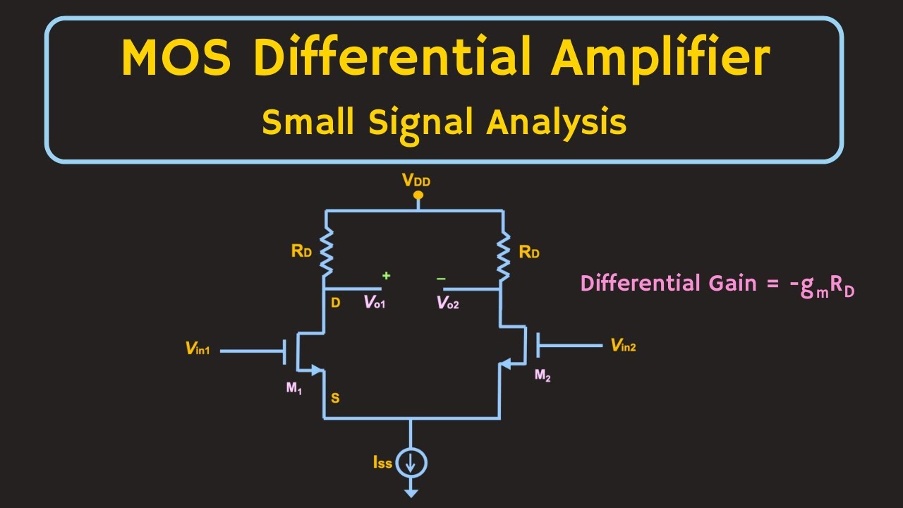
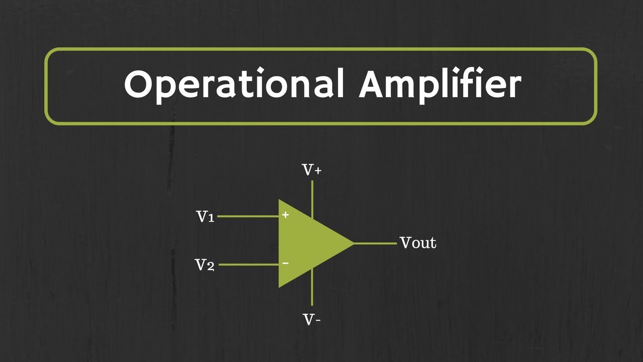
- ๐ Differential amplifiers are designed to amplify the difference between two input signals, V1 and V2, with the output (V_out) being proportional to this difference.
- ๐ง The explanation assumes an ideal operational amplifier (opamp), characterized by no current flowing into its input terminals and equal voltages at the non-inverting and inverting terminals.
- ๐ฌ The superposition principle is used to analyze the circuit's behavior by considering one input at a time while grounding the other.
- ๐ When V2 is grounded (shorted), the circuit behaves as an inverting amplifier, and the output voltage (V_out1) is calculated based on the input V1 and the resistor values.
- ๐ Reintroducing V2 but grounding V1 allows the calculation of V_out2, which is the output voltage solely due to V2, considering the voltage division across resistors R2 and RG.
- ๐ข The overall output voltage (V_out) is the sum of the individual effects of V1 and V2 on the output, as derived from the resistor ratios and input voltages.
- ๐ก In a special case where all resistors are equal, the output voltage is exactly the difference between V2 and V1, simplifying the amplifier's behavior.
- ๐ง Another special configuration is when R1 equals R2 and RF equals RG, but they are not necessarily the same, which results in a gain factor being applied to the difference between the input voltages.
- ๐ The tutorial concludes by reinforcing the understanding of differential amplifiers and hints at further learning in subsequent videos.
Q & A
What is the main difference between a differential amplifier and a differentiator?
-A differential amplifier takes the difference between two input signals, whereas a differentiator, also built with op-amps, takes the derivative of an incoming signal.
What assumptions does David Williams make about the op-amp in his explanation?
-David Williams assumes that the op-amp is ideal, meaning that the voltage at the non-inverting terminal is equal to the voltage at the inverting terminal, and that no current flows into either terminal.
How does the superposition principle relate to the explanation of the differential amplifier?
-The superposition principle is used to analyze the output of the differential amplifier in relation to one input at a time, assuming the other input is grounded, and then combining the effects to understand the overall behavior.
What is the significance of the voltage at the non-inverting terminal being equal to the voltage at the inverting terminal in an ideal op-amp?
-In an ideal op-amp, this equality implies that the input impedance is infinite, and thus no current flows into the inputs, which simplifies the analysis of the circuit.
How does the current through R1 relate to the current through RF in the ideal op-amp model?
-In the ideal op-amp model, the current through R1 is equal to the current through RF because the inverting terminal is at a virtual ground, and the currents through the feedback network must be conserved.
What is the expression for V_out1 when only V1 is considered in the differential amplifier circuit?
-V_out1 is equal to -(RF/R1) * V1, which represents the output voltage due to V1 when V2 is shorted to ground.
How is V_out2 determined when only V2 is considered in the differential amplifier circuit?
-V_out2 is determined by the voltage at the non-inverting terminal, which is V2 * RG/(R2 + RG), and is then used to find the output voltage using the relationship between the currents through R1 and RF.
What is the overall expression for V_out in terms of V1 and V2 when both inputs are considered?
-The overall V_out is the sum of the individual effects of V1 and V2 on the output, which is V_out = V2 * (RG/(R2 + RG) * (R1 + RF)/R1) - V1 * (RF/R1).
In what special case would the output voltage V_out be exactly the difference between V2 and V1?
-The output voltage V_out would be exactly the difference between V2 and V1 if all resistors (R1, R2, RF, RG) are equal in value.
What is the significance of the resistor values in determining the gain of the differential amplifier?
-The resistor values determine the gain of the differential amplifier by setting the ratio of the feedback resistor to the input resistor, which can amplify or attenuate the difference between the input voltages.
Outlines
๐ฌ Introduction to Differential Amplifiers
David Williams, an instructor in electronic engineering technology at Okanogan College, introduces the concept of differential amplifiers, distinguishing them from differentiators. He clarifies that differential amplifiers are designed to amplify the difference between two input signals, V1 and V2, rather than taking the derivative of a signal. The output voltage (V_out) is proportional to the difference between these inputs. Williams sets the stage for a deeper exploration of the differential amplifier's operation by assuming an ideal operational amplifier (opamp) with no current flowing into its terminals and equal voltages at the non-inverting and inverting terminals. He then uses the superposition principle to analyze the output's relationship to each input individually, with the other input grounded.
๐งฎ Analyzing Differential Amplifier Output
In the second paragraph, Williams delves into the mathematical analysis of the differential amplifier's output. He first considers the scenario where V2 is grounded, effectively turning the circuit into a simple inverting amplifier. From this setup, he derives that V_out1 (the output due to V1 alone) is equal to negative RF/R1 times V1. Next, he examines the case where V1 is grounded, focusing on how V_out2 (the output due to V2 alone) is determined. He finds that the voltage at the non-inverting terminal is a function of V2, split between R2 and RG, and uses this to derive an expression for V_out2. By combining the effects of both V1 and V2, Williams presents a comprehensive formula for the overall V_out, which is a function of the resistor ratios and the difference between V2 and V1. He concludes by discussing special cases, such as when all resistors are equal or when R1 equals R2 and RF equals RG, and how these affect the differential amplifier's gain and output.
Mindmap
Keywords
๐กDifferential Amplifier
๐กOpamp
๐กIdeal Opamp Assumptions
๐กSuperposition Principle
๐กNon-Inverting Terminal
๐กInverting Terminal
๐กVirtual Ground
๐กResistor Ratios
๐กFeedback
๐กVoltage Divider
Highlights
Introduction to differential amplifiers and their distinction from differentiators.
Explanation of how differential amplifiers output is proportional to the difference between V2 and V1.
Assumption of an ideal opamp with no current flowing into its terminals.
Use of the superposition principle to analyze the output in relation to the inputs.
Analysis of the circuit when V2 is grounded to find the output V_out1.
Derivation of V_out1 formula as V_out1 = -RF/R1 * V1.
Reintroduction of V2 and shorting of V1 to find V_out2.
Calculation of voltage at the non-inverting terminal based on V2.
Derivation of V_out2 formula considering the voltage divider principle.
Final expression for V_out as a function of the difference between V2 and V1.
Special case analysis when all resistors are equal, resulting in V_out being the difference between V2 and V1.
Another special case where R1 equals R2 and RF equals RG, leading to a gain applied to the input difference.
Practical application of differential amplifiers in electronic engineering.
Educational approach to understanding differential amplifiers through step-by-step analysis.
Importance of ideal opamp assumptions in simplifying circuit analysis.
Conclusion and anticipation for the next video in the series.
Transcripts
hi there I'm David Williams I'm an
instructor in the electronic engineering
technology department at Okanogan
college and I want to show you today how
differential amplifiers work now don't
confuse differential amplifiers with
differentiators which can also be built
with opamps differentiators take the
derivative of an incoming signal whereas
these differential amplifiers are going
to take the difference or there the
output anyway is going to be the output
here V out is going to be proportional
to the difference between V2 and V1 and
what I want to show you is how that
relationship comes about so here's my
circuit again and in order to show how
the output is proportional to the
difference between V2 and V1 I'm going
to make a couple of assumptions about
this opamp and and basically I'm going
to assume that this opamp is ideal so
what those assumptions mean or what an
ideal opamp means especially or
considering this one that has a feedback
going from the output back to the in
inverting
input the voltage at the non-inverting
terminal so that's the voltage here with
respect to ground is going to be equal
to the voltage at the inverting terminal
so that's the voltage here with respect
to
ground and the other assumption that I'm
going to need to make use of is that no
current flows into either one of these
terminals no current into the inverting
terminal no current into the
non-inverting terminal and so what that
means is the current through R1
there
is going to be equal to the current
through this RF
here it also means that the current
through this R2 resistor is going to be
equal to the current through the RG
resistor so I'm going to have these
three conditions imposed on The Circuit
by assuming that my opamp here is
ideal now in order to see how the output
relates to the two input over here we're
going to have to make use of one way to
go about doing this is to make use of
the superposition principle so what
we're going to do is see what the output
is in relationship to one of the inputs
assuming that the other input is
grounded and then do the same thing for
the other input see how the output
output is in relationship to V1 here
when V2 V2 is is zero and then when we
put the two of the sum of those two
signals together the sum of those two
voltages together we'll get an overall
picture of what's what's going on in the
circuit so the first thing I'm going to
do is just look at the output look at
the output when is just V1 so I'm going
to short V2 so that means this voltage
here at V2 is grounded is ground and
so what is the output when it's only V
only considering
V1 so in this case if we short V2 here
well that's going to end up making the
non-inverting terminal ground so this
point is is ground and we end up with
just the just an inverting an inverting
amplifier and so we will
have ir1 is equal to I
RF since this point is is virtual ground
ir1 will be V1 over
R1 and again since this is virtual
ground the voltage across RF will be 0
minus V out which is just negative V
out / by
RF and we can rearrange this equation
and we get V
out is equal
to RF over
R1 time V1 so I guess we should call
this V
out1 because this is just the V out due
to V1 so V out1 is equal to negative RF
over R1 * V1
now what if we reintroduce V2 but we
short V1 so now V1 is connected to
ground
here so we short
V1 and what we want to do is find out
what V out is when V when V1 is shorted
so we'll call this V out2 this is just
when V out is dependent only only on V2
so now what we want to do is figure out
what V out2 is when when it's just V1
when when V1 is shorted and it's just V2
here being
applied so again the inverting terminal
and the non-inverting terminal are going
to be the at the same voltage so we
could actually figure out what the
voltage at this point is in terms of V2
so at the non-inverting terminal that
voltage is equal to V2 * RG over R2 plus
RG right because V2 is across both R2
and RG and so it's going to be split
between R2 and RG and the proportion
that split depends on the values of
those two resistors so v v voltage at
the non-inverting terminal terminal will
be equal to V2 *
RG over R2 +
RG and since we have this negative
feedback here the voltage at the
inverting terminal is going to be equal
to the voltage at the non inverting
terminal now we know the voltage at this
point and so we can use the fact that we
will have current going through R1 and
RF those two currents are going to be
equal so we can find out V out in we can
find out the voltage at this point in
terms of a v
out now we can find the voltage at the
inverting terminal in terms of V out
because this voltage is based on what
the V out is and it's based on the
voltage divider between r R1 and RF so V
at voltage at the inverting terminal is
equal to V
out * R1 over R1 +
RF so we've got one expression here for
the inverting terminal voltage and
another expression here for the voltage
at the inverting terminal so we can set
those two equal to each other we'll have
V2 * RG over r2+
RG is equal to
V out * R1 over R1 +
RF now the trick is we want to we want
just have this expression in terms of V
out and I guess this is the V out2
because only due to the voltage from
from uh
V2 so just rearranging this expression V
out2 is equal to
V2 *
rg/ r R2 +
RG * R1 +
RF over R1 so there's my expression for
V
out2 now the overall V
out is equal to the voltage due to V2
voltage at the output due to V2 which is
this expression plus the voltage at V
out due to V1 which is this expression
and so we get V out is equal to
V2 times all of these resistor ratios
here RG over R2 +
RG time R1 +
RF over
R1
minus V1 * RF over
R1 now this is may look like a really
big expression but you can see here that
I mean it if these if these resistors
are set that's just a number that's just
a number multiplying V2 so it's some
some number times V2 minus again RF over
R1 that's just going to be some number
based on the resistors some number times
V1 so V out is based on the some number
time V2 minus some number time V1 so
it's proportional essentially
proportional to the difference between
V2 and
V1 now in the special case where all of
these resistors are equal to each other
so we've got R1 is equal to R2 is equal
to RF is equal to
RG then you'll see this will be 1 over 1
over 2 * 2 over 1 so that will just be
equal to one that this big resistor
expression will be equal to one and this
resistor expression will also be equal
to one so if all those resistors are
equal to each other then the output
voltage will be just the difference
between V2 and
V1 so there's the differential
amplifier another special
case is if R1 is equal to R2 and at the
same time RF is equal to RG but R2 and
RF are not necessarily the same values
so these these this would be one value
and these two resistors would be another
value what we would get is V
out is equal to
some gain which is RF over R1 times the
difference between V2 and V1 so you can
do the diff to do the difference between
those two input voltages but then also
apply some amount of gain based on based
on this
ratio so hopefully you learned a little
bit about differential amplifiers and
I'll see you in the next
video
Browse More Related Video
Op-Amp: Summing Amplifier (Inverting and Non-Inverting Summing Amplifiers)
MOSFET - Differential Amplifier (Small Signal Analysis)
Resistors in Series and Parallel Circuits Experiment - GCSE Physics Required Practical
Multistage Amplifier: Design Example
Active Low Pass Filter - EXPERIMENT
Common-Collector Configuration of a Transistor
5.0 / 5 (0 votes)