Electrical Engineering: Basic Laws (12 of 31) Kirchhoff's Laws: A Harder
Summary
TLDRThis video explains how to solve a circuit problem using Kirchhoff's rules, particularly when multiple loops and voltage sources are involved. The speaker walks through determining the currents in various branches of the circuit, assuming initial directions for the currents, and formulating equations based on Kirchhoff's current and voltage laws. The process involves solving three equations to find the unknown currents, and adjusting for any negative results indicating opposite directions. The video concludes with calculated values for the currents in each branch, demonstrating the effective use of Kirchhoff's rules.
Takeaways
- 🔋 Kirchhoff's rules are ideal for analyzing circuits with multiple loops and voltage sources.
- 🔄 Assume a current direction in each branch; incorrect assumptions will lead to a negative result, indicating the opposite direction.
- ⚡ Kirchhoff's Current Law states that the sum of currents entering a node equals the sum of currents leaving the node.
- 🔁 Kirchhoff's Voltage Law says that the sum of all voltages around any closed loop should equal zero.
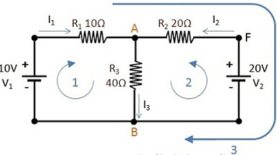
- 🌀 The circuit consists of three loops with currents I1, I2, and I3 flowing through 4Ω, 6Ω, and 8Ω resistors.
- 📐 For loop 1, the voltage equation is based on a 10V battery and resistors, resulting in: I1 + I3 = I2.
- ➕ For loop 2, the equation involves voltage drops and rises across the resistors and batteries, giving: 8I1 + 6I3 = -4.
- ➖ When simplifying and solving, the current I3 turns out to be negative, meaning the direction is opposite to the initial assumption.
- 🔍 Solving for I2 and I1 using substitution and combining equations results in positive values for these currents.
- ✅ Final results: I1 = 1.039 A, I2 = 0.731 A, I3 = -0.308 A, confirming the analysis using Kirchhoff's laws.
Q & A
What are Kirchhoff's rules, and why are they useful for solving this type of circuit problem?
-Kirchhoff's rules consist of two laws: Kirchhoff's current law (KCL) states that the sum of currents entering a node equals the sum of currents leaving the node. Kirchhoff's voltage law (KVL) states that the sum of all voltages around any closed loop in a circuit is zero. They are useful for solving circuits with multiple loops and voltage sources, like the one in this problem, where determining individual branch currents can be complex.
How are the current directions initially assumed in this circuit?
-The current directions are assumed based on the orientation of the voltage sources. For the branch with the 10V battery, current is assumed to flow clockwise (I1). For the branch with the 4V battery, current is assumed to flow clockwise (I3). If these assumptions are incorrect, the final calculated current values will simply be negative, indicating that the actual current flows in the opposite direction.
What are the main steps to solve for the currents using Kirchhoff's rules in this problem?
-1. Assume the direction of current in each branch (I1, I2, and I3). 2. Apply Kirchhoff's current law at a node to get the relationship between the currents. 3. Apply Kirchhoff's voltage law to two independent loops to form two more equations. 4. Solve the system of three equations to find I1, I2, and I3.
How is Kirchhoff's current law applied in this circuit?
-Kirchhoff's current law is applied at the top node, where the currents I1 and I3 enter the node, and I2 leaves the node. This gives the equation I1 + I3 = I2.
How is Kirchhoff's voltage law applied to loop 1?
-For loop 1, Kirchhoff's voltage law is applied by summing the voltage changes around the loop: starting at the 10V battery (positive), moving through the 4-ohm resistor (voltage drop of -4I1), and then through the 8-ohm resistor (voltage drop of -8I2). The total sum must equal zero, forming the equation 10 - 4I1 - 8I2 = 0.
How is Kirchhoff's voltage law applied to loop 2?
-For loop 2, Kirchhoff's voltage law is applied by summing the voltage changes: starting with the 8-ohm resistor (voltage rise of +8I2), moving through the 6-ohm resistor (voltage rise of +6I3), and then across the 4V battery (voltage drop of -4V). This gives the equation 8I2 + 6I3 - 4 = 0.
What is the significance of a negative current value after solving the equations?
-A negative current value indicates that the assumed direction for that current is opposite to the actual direction. For instance, if I3 is negative, it means the current flows in the opposite direction to what was initially assumed.
How do the equations change after substituting I2 in terms of I1 and I3?
-After substituting I2 = I1 + I3 into the voltage equations, the new equations become: 10 - 4I1 - 8(I1 + I3) = 0 and 8(I1 + I3) + 6I3 - 4 = 0. These are simplified to solve for I1 and I3.
What is the final value of current I3, and what does its negative sign imply?
-The final value of I3 is -0.308 amps. The negative sign implies that the actual direction of the current is opposite to the assumed clockwise direction in loop 2.
What are the final values of the currents I1 and I2?
-The final value of I1 is 1.039 amps, and the final value of I2 is 0.731 amps. Both currents flow in the assumed directions.
Outlines

Этот раздел доступен только подписчикам платных тарифов. Пожалуйста, перейдите на платный тариф для доступа.
Перейти на платный тарифMindmap

Этот раздел доступен только подписчикам платных тарифов. Пожалуйста, перейдите на платный тариф для доступа.
Перейти на платный тарифKeywords

Этот раздел доступен только подписчикам платных тарифов. Пожалуйста, перейдите на платный тариф для доступа.
Перейти на платный тарифHighlights

Этот раздел доступен только подписчикам платных тарифов. Пожалуйста, перейдите на платный тариф для доступа.
Перейти на платный тарифTranscripts

Этот раздел доступен только подписчикам платных тарифов. Пожалуйста, перейдите на платный тариф для доступа.
Перейти на платный тарифПосмотреть больше похожих видео

Aula 2. Leis De Kirchhoff Exercício 1
HUKUM II KIRCHHOFF
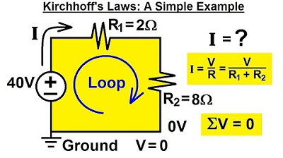
Electrical Engineering: Basic Laws (9 of 31) Kirchhoff's Laws: A Simple Example

Pushing a voltage source through a node

Superposition Examples (Circuits for Beginners #14)

Electrical Engineering: Basic Laws (11 of 31) Kirchhoff's Laws: A Medium Example 2
5.0 / 5 (0 votes)
