FEA 23: 2-D Triangular Elements
Summary
TLDRThis video script offers a comprehensive guide to developing a 2D linear triangular element in structural analysis. It covers defining displacement and strain fields, setting up element geometry and degrees of freedom, and establishing shape functions. The script delves into deriving the B matrix and D matrix for stress-strain relationships, culminating in the stiffness matrix formulation. It also addresses handling distributed forces, distinguishing between body and surface forces, and calculating elemental force vectors, providing a foundational understanding of finite element analysis.
Takeaways
- 📐 The video focuses on the development of a 2D triangular linear element, specifically a right triangle with a 90-degree corner.
- 🔍 It emphasizes the importance of defining the displacement field, strain, and stress fields for the element.
- 🌐 The element's geometry and degrees of freedom are defined, which are crucial for relating back to the displacement field vector.
- 📏 A shape function matrix is established to define how the displacement field varies within the element.
- 🔗 The relationship between the strain vector and the displacement field vector U is explored, leading to the partial derivative matrix operator.
- 📚 The D matrix, which contains material properties, is derived from the relationship between stress and strain.
- 🧮 Matrix multiplication of the partial derivative matrix and the shape function matrix results in the B matrix.
- 🔑 The stiffness matrix K of the element is calculated using B and D matrices.
- 💪 The element force vector is discussed, including how to account for distributed forces acting on the element.
- 🔄 The concept of transformation from local to global coordinate systems is introduced but will be detailed in later videos.
- 📉 The script uses a specialized right triangle element to simplify the development process and focus on the methodology.
Q & A
What is the focus of the short video introduced in the transcript?
-The short video focuses on introducing 2D elements, specifically the three-noded triangular linear element, and discusses the process of defining a new element in finite element analysis.
What are the initial decisions one needs to make when defining a new element?
-When defining a new element, one needs to decide on the displacement field of interest, the element geometry, the degrees of freedom, and how the displacement field varies within the element.
What is a degree of freedom vector in the context of this video?
-A degree of freedom vector relates back to the displacement field vector and consists of six terms for a three-noded triangle element, with each node having two degrees of freedom for horizontal and vertical displacement.
Why is the shape function matrix important in the development of an element?
-The shape function matrix is crucial as it defines how the displacement field varies within the element and how that variation relates back to the degrees of freedom.
What does the partial derivative matrix operator represent in the context of this video?
-The partial derivative matrix operator represents the relationship between the strain vector and the displacement field vector U.
What is the D matrix and how is it derived?
-The D matrix represents the relationship between stress and strain, incorporating material properties. It is derived from the stress-strain relationship for a given material under plane stress or plane strain conditions.
Why is the B matrix significant in finding the stiffness matrix of an element?
-The B matrix is significant because it is the product of the partial derivative matrix operator and the shape function matrix, which is then used to calculate the stiffness matrix K.
How is the stiffness matrix K for a new element calculated?
-The stiffness matrix K is calculated by integrating the product of B transpose and D matrices over the volume of the element.
What is the significance of the element force vector in the context of this video?
-The element force vector represents the forces acting on the element, which when added to the nodal forces, gives the global force vector.
Why is the right triangle element chosen for the development process in the video?
-The right triangle element is chosen because it simplifies the development process by limiting the complexity of the math involved in defining the position of the three points, allowing the focus to be on the development process itself.
How does the video script differentiate between body forces and surface forces?
-Body forces are forces that act throughout the volume of the element, while surface forces act along the edges or surface of the element. The script uses an example of a uniformly distributed downward acting body force and a surface traction force at a 45-degree angle to illustrate this.
Outlines

Этот раздел доступен только подписчикам платных тарифов. Пожалуйста, перейдите на платный тариф для доступа.
Перейти на платный тарифMindmap

Этот раздел доступен только подписчикам платных тарифов. Пожалуйста, перейдите на платный тариф для доступа.
Перейти на платный тарифKeywords

Этот раздел доступен только подписчикам платных тарифов. Пожалуйста, перейдите на платный тариф для доступа.
Перейти на платный тарифHighlights

Этот раздел доступен только подписчикам платных тарифов. Пожалуйста, перейдите на платный тариф для доступа.
Перейти на платный тарифTranscripts

Этот раздел доступен только подписчикам платных тарифов. Пожалуйста, перейдите на платный тариф для доступа.
Перейти на платный тарифПосмотреть больше похожих видео
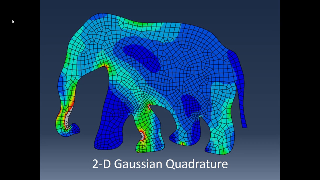
FEA 30: 2-D Gaussian Quadrature
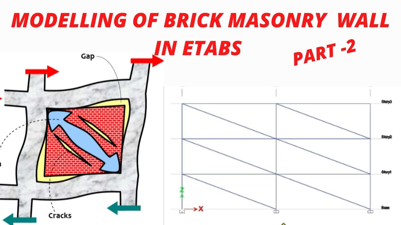
MODELLING OF BRICK MASONRY WALL IN ETABS ,STRUT ANALOGY, (PART -2)

Praktikum Geologi Struktur 2024 - Modul 3. Proyeksi Stereografi - 1. Prinsip Dasar

FEA 24: 2-D Rectangular Elements

METODE MATRIKS KEKAKUAN #2, Metode Matriks Kekakuan, Plane Truss Structures, Struktur Rangka Bidang

What is Finite Element Analysis? FEA Explained
5.0 / 5 (0 votes)
