TUTORIAL - KONFIGURASI VLAN PADA CISCO PACKET TRACER - 2022
Summary
TLDRIn this tutorial, Riswan demonstrates how to configure a Virtual Local Area Network (VLAN) using Cisco Packet Tracer. He starts by setting up a simple network with four computers and a switch, then explains how to assign IP addresses to each computer. Riswan proceeds to configure two VLANs, explaining the process through the command-line interface (CLI), including defining VLAN IDs and linking interfaces to specific VLANs. He concludes by showing how the VLANs isolate communication between devices in different VLANs, ensuring only devices within the same VLAN can communicate.
Takeaways
- 😀 The tutorial introduces the concept of Virtual Local Area Networks (VLANs) and demonstrates how to configure them using Cisco Packet Tracer.
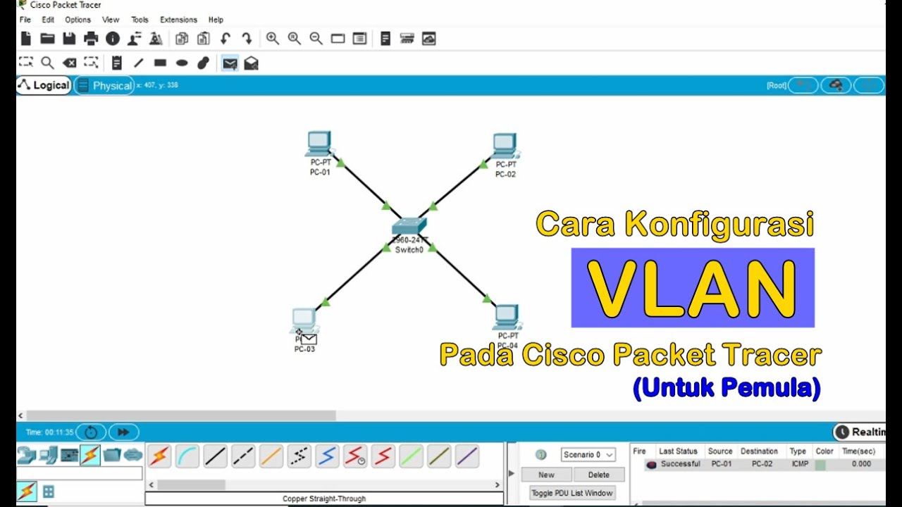
- 😀 The video starts by explaining the setup of a basic network with a switch and four computers (PC1, PC2, PC3, and PC4).
- 😀 The computers are connected to the switch using straight-through cables and are initially configured with basic IP addresses (e.g., 192.168.1.1, 192.168.1.2, etc.).
- 😀 The main goal of the tutorial is to configure VLANs to separate traffic within the same physical network, creating virtual network partitions.
- 😀 Two VLANs are created: VLAN 10 (named 'kiri') and VLAN 20 (named 'kanan').
- 😀 Before configuring the VLANs, the computers in the network are able to ping each other, indicating they are in the same LAN.
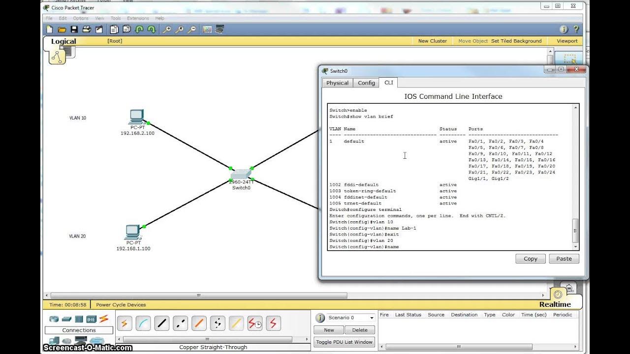
- 😀 The configuration is done using the Command Line Interface (CLI) in Cisco Packet Tracer, where commands such as 'enable' and 'configure terminal' are used to access configuration mode.
- 😀 VLAN interfaces are created by defining the VLAN IDs and assigning names (e.g., VLAN 10 and VLAN 20).
- 😀 Switch ports are then assigned to specific VLANs using commands like 'switch access vlan' and 'switchport mode access'.
- 😀 After the configuration, communication between computers in different VLANs is blocked, while computers within the same VLAN (e.g., PC1 and PC2) can still communicate.
- 😀 The tutorial concludes with a demonstration of the VLAN setup, ensuring that only devices in the same VLAN can communicate with each other, while devices in different VLANs cannot.
Q & A
What is the purpose of this video tutorial?
-The purpose of this video is to demonstrate how to configure Virtual LANs (VLANs) using the Cisco Packet Tracer application.
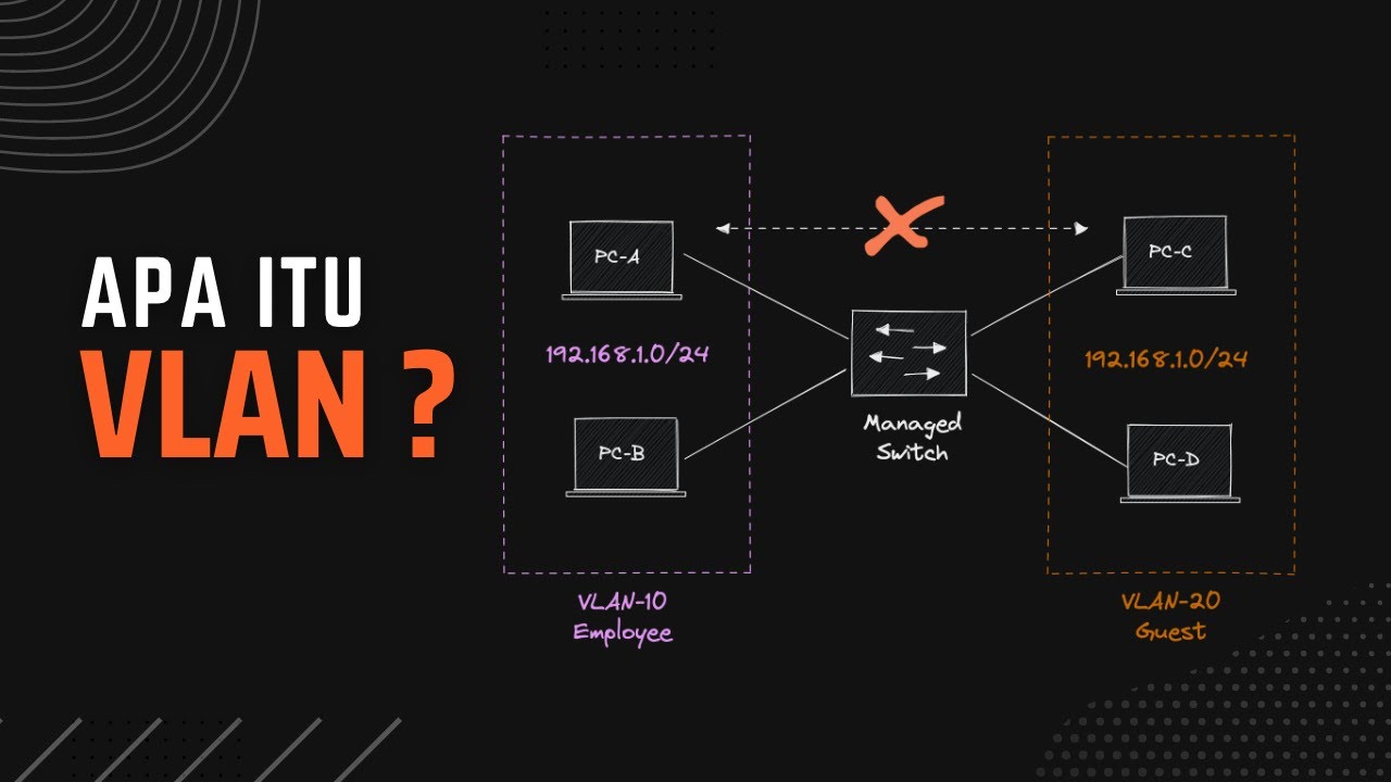
What is a Virtual Local Area Network (VLAN)?
-A Virtual Local Area Network (VLAN) is a logical partition of a physical network, which allows devices in different physical locations to communicate as if they were on the same network.
What devices are used in the setup for this tutorial?
-The tutorial uses a Cisco 2950 series switch and four computers (PCs).
How are the computers connected to the switch?
-The computers are connected to the switch using straight-through cables, with each computer connected to a different port on the switch.
What IP addresses are assigned to the computers?
-The computers are assigned IP addresses as follows: PC1 - 192.168.1.1, PC2 - 192.168.1.2, PC3 - 192.168.1.3, and PC4 - 192.168.1.4, all with the subnet mask 255.255.255.0.
What is the purpose of defining VLAN IDs in the switch configuration?
-Defining VLAN IDs allows the switch to logically separate the network into different broadcast domains, which helps in managing network traffic and increasing security by isolating communication between different groups of devices.
How are the VLANs configured in the Cisco switch?
-VLANs are configured in the switch by defining the VLAN IDs using the command line interface (CLI). The first VLAN has ID 10 and the second VLAN has ID 20. The command 'switch access vlan' is used to assign interfaces to these VLANs.
What command is used to create VLANs in the switch?
-The command 'vlan [ID]' is used to create a VLAN in the switch's configuration mode. For example, 'vlan 10' creates VLAN 10.
Can computers from different VLANs communicate with each other by default?
-No, computers from different VLANs cannot communicate with each other by default. Communication is only possible between devices within the same VLAN.
How is the switch configured to assign ports to VLANs?
-Ports on the switch are assigned to VLANs by using the command 'switchport access vlan [ID]' in the interface configuration mode. For example, 'switchport access vlan 10' assigns the interface to VLAN 10.
Outlines

このセクションは有料ユーザー限定です。 アクセスするには、アップグレードをお願いします。
今すぐアップグレードMindmap

このセクションは有料ユーザー限定です。 アクセスするには、アップグレードをお願いします。
今すぐアップグレードKeywords

このセクションは有料ユーザー限定です。 アクセスするには、アップグレードをお願いします。
今すぐアップグレードHighlights

このセクションは有料ユーザー限定です。 アクセスするには、アップグレードをお願いします。
今すぐアップグレードTranscripts

このセクションは有料ユーザー限定です。 アクセスするには、アップグレードをお願いします。
今すぐアップグレード関連動画をさらに表示
Tutorial - Cara Konfigurasi VLAN pada Cisco Packet Tracer (Untuk Pemula)
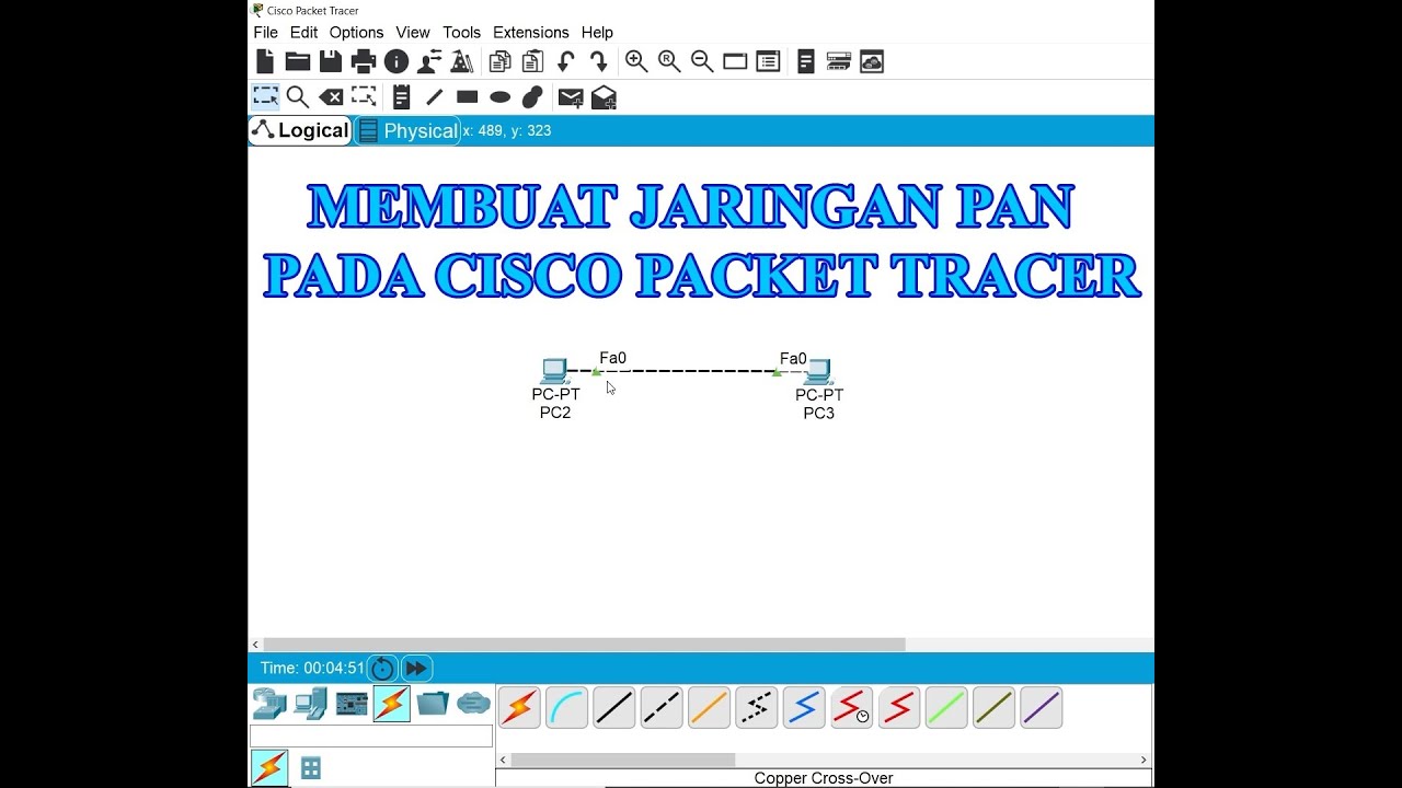
Membuat Jaringan PAN pada Cisco Packet Tracer

Netzwerktutorial: Cisco Packet Tracer - Installation, Konfiguration & ein erster Aufbau

Basics of Cisco Packet Tracer (Part 2) | Hub
Belajar VLAN (Virtual LAN) | Konfigurasi VLAN Pada Perangkat Cisco
Single Switch VLAN in Packet Tracer
5.0 / 5 (0 votes)
