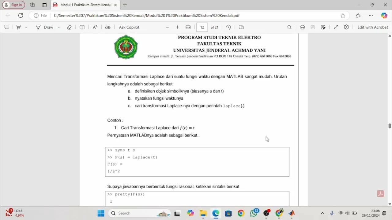
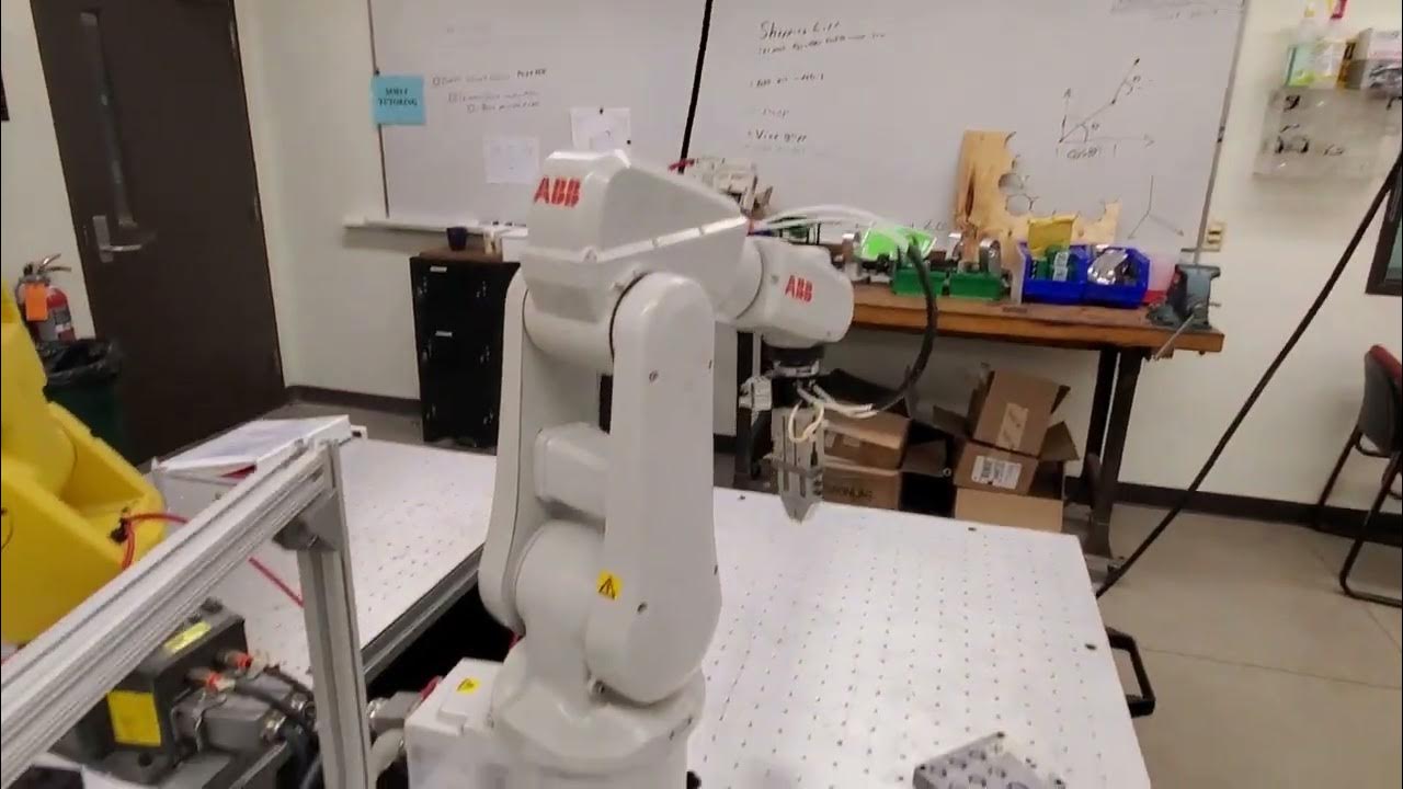
How to Make Simulation of Inverted Pendulum (Balancing Robot) Control in Simulink Matlab
Summary
TLDRIn this video tutorial, the presenter walks through the process of simulating a balancing robot using an inverted pendulum control system in MATLAB/Simulink. Key topics include system modeling, state feedback control, and the implementation of a state feedback matrix using the Linear Quadratic Regulator (LQR) method. The presenter explains the steps to build a simulation in Simulink, applying control strategies to stabilize the pendulum. The tutorial emphasizes the importance of adjusting system parameters and initial conditions to achieve system stability. It's an insightful guide for anyone studying control systems or robotic simulations.
Takeaways
- 😀 The video introduces a simulation of a balancing robot based on the inverted pendulum principle, using state feedback control in Simulink/Matlab.
- 😀 The inverted pendulum model is explained as a classic control problem where the goal is to stabilize the pendulum in an upright position.
- 😀 The presenter mentions the importance of system modeling, highlighting key matrices (A, B) and state feedback as crucial components for the control design.
- 😀 To begin the simulation, the user must open Matlab, create a Simulink project, and set up the system using appropriate matrices and gain blocks.
- 😀 The feedback matrix in the simulation is essential for regulating the system’s response to errors and ensuring stability.
- 😀 A significant part of the setup involves adjusting the state feedback values, such as multiplying by negative numbers, to correct the system's behavior.
- 😀 Initial conditions like the angular position and velocity of the pendulum need to be set before running the simulation.
- 😀 The presenter highlights troubleshooting, where changes were made to system parameters and feedback values to improve the simulation results.
- 😀 The simulation results show the state variables converging to zero, indicating that the robot has reached a stable equilibrium position.
- 😀 The video serves as an educational resource for students and engineers interested in learning about balancing robots and control systems using state feedback.
- 😀 The presenter ends with gratitude for the viewers’ attention and invites questions, while apologizing for any presentation delays or errors.
Q & A
What is the main focus of the video?
-The main focus of the video is to demonstrate how to simulate and control a balancing robot with an inverted pendulum using state feedback control in MATLAB Simulink.
What system is being modeled in this video?
-The system being modeled is a balancing robot that uses the principle of an inverted pendulum, where the pendulum needs to be controlled to stay upright.
What is the role of state feedback control in this simulation?
-State feedback control stabilizes the balancing robot by using feedback from the system’s state variables (e.g., position, angle) to adjust the control inputs and maintain balance.
What are the key steps in setting up the simulation in Simulink?
-The key steps include: opening Simulink, creating a project, adding the appropriate blocks (like gain blocks and matrix blocks), configuring the system model with matrices, and setting up the simulation parameters such as initial conditions and the state feedback controller.
What matrices are used to represent the system in state-space modeling?
-The matrices used in state-space modeling are the A, B, and N matrices, which describe the system’s dynamics and input-output relationships.
Why is state feedback control necessary for this system?
-State feedback control is necessary because it allows for real-time adjustments based on the system's current state (like the angle of the pendulum), ensuring that the robot maintains balance and stabilizes the inverted pendulum.
What troubleshooting steps are mentioned for resolving simulation issues?
-The troubleshooting steps mentioned include checking the matrix sizes, ensuring proper parameter multiplication (especially with the gain matrix), and confirming that initial conditions are correctly set to avoid simulation errors.
What initial condition is specified for the simulation of the inverted pendulum?
-The initial condition specified is the angular position of the pendulum, which is set to a value of 1, representing the starting angle of the pendulum before the simulation begins.
What is the purpose of the gain matrix in state feedback control?
-The gain matrix in state feedback control determines how much influence each state variable (such as position or angle) has on the control input. It is used to compute the corrective actions needed to stabilize the system.
How does the simulation show the behavior of the balancing robot?
-The simulation shows the behavior of the balancing robot by displaying the state variables over time. The goal is to observe the pendulum moving toward a stable position, with the simulation output showing the state variables converging to zero, indicating balance.
Outlines

このセクションは有料ユーザー限定です。 アクセスするには、アップグレードをお願いします。
今すぐアップグレードMindmap

このセクションは有料ユーザー限定です。 アクセスするには、アップグレードをお願いします。
今すぐアップグレードKeywords

このセクションは有料ユーザー限定です。 アクセスするには、アップグレードをお願いします。
今すぐアップグレードHighlights

このセクションは有料ユーザー限定です。 アクセスするには、アップグレードをお願いします。
今すぐアップグレードTranscripts

このセクションは有料ユーザー限定です。 アクセスするには、アップグレードをお願いします。
今すぐアップグレード関連動画をさらに表示

Tuning PID di Simulink

Modul A1 Demo Praktikum Sistem Kendali

Simulink Control Systems and PID, Matlab R2020b

How to Design Load Frequency Control using Simulink ? | Dr. J. A. Laghari

SISTEM KONTROL - Part 3.1 : Pemodelan Sistem

Introduction to ABB Robot Coding- Write a Simple Code for Moving and Closing the Gripper
5.0 / 5 (0 votes)
