MOD 60 using 7490
Summary
TLDRThis video tutorial explains how to design a Mode 60 counter circuit using the 7490 integrated circuit and a 555 timer. It details the connections required for the 7490 to count from 00 to 59 in Binary Coded Decimal (BCD) format, with optional output display configurations using LEDs or a 7447/7448 display driver. The presenter guides viewers through the circuit assembly on a breadboard, demonstrating the function of each component and how to generate clock pulses with a push button. The summary highlights the practical steps needed for building the counter and encourages viewers to engage with the content.
Takeaways
- 😀 The mode 60 counter is designed to count from 00 to 59 using the 7490 binary-coded decimal (BCD) counter IC.
- 🕰️ The 555 timer IC is configured in astable mode to generate continuous clock pulses for the counter.
- 🔌 The clock input for the 7490 is connected to pin 14, receiving pulses from the timer.
- 💡 Output pins of the 7490 (pins 12, 9, 8, 11) represent BCD outputs A, B, C, and D, respectively.
- 🔄 The counter resets to 00 after reaching 59, allowing continuous counting.
- 🖥️ LEDs can be used to visualize the counting process by connecting to the output pins of the 7490.
- 🔘 A push button switch is used to manually trigger clock pulses, controlling the counting increment.
- 📟 To integrate a display, use IC 7447 for common anode or IC 7448 for common cathode displays.
- 🔗 The outputs from the 7490 are directly connected to the display driver IC for visual representation.
- ⚡ The circuit includes proper power supply and grounding connections for stable operation.
Q & A
What is the purpose of the 7490 IC in the circuit?
-The 7490 IC is used as a BCD counter, which counts from 00 to 59 in Binary Coded Decimal format.
How does the clock pulse affect the operation of the counter?
-The clock pulse, generated by the 555 timer IC in astable mode, triggers the counter to increment its count each time the pulse is received.
What are the output pins of the 7490 IC and their corresponding labels?
-The output pins of the 7490 IC are pin 12 (Output A), pin 9 (Output B), pin 8 (Output C), and pin 11 (Output D).
How is the 555 timer configured in this circuit?
-The 555 timer is configured in astable mode to continuously generate clock pulses.
What additional components are needed to visualize the output count?
-LEDs or a display IC, such as the 7447 for common anode displays or 7448 for common cathode displays, are needed to visualize the output count.
How does the push-button switch integrate into the circuit?
-The push-button switch is connected to the clock input of the 555 timer, allowing the user to generate a clock pulse when pressed.
What happens when the counter reaches 59?
-When the counter reaches 59, it resets to 00 and continues counting up again.
Why is it necessary to use current-limiting resistors with the display?
-Current-limiting resistors are necessary to prevent excessive current from flowing through the display, which could damage it.
What are the benefits of using a BCD counter like the 7490?
-Using a BCD counter simplifies the process of counting in decimal format and allows for easy integration with digital displays.
Can this circuit be adapted for counting beyond 59?
-While this circuit is designed for counting from 00 to 59, modifications could be made to accommodate larger numbers, but that would require additional circuitry.
Outlines

このセクションは有料ユーザー限定です。 アクセスするには、アップグレードをお願いします。
今すぐアップグレードMindmap

このセクションは有料ユーザー限定です。 アクセスするには、アップグレードをお願いします。
今すぐアップグレードKeywords

このセクションは有料ユーザー限定です。 アクセスするには、アップグレードをお願いします。
今すぐアップグレードHighlights

このセクションは有料ユーザー限定です。 アクセスするには、アップグレードをお願いします。
今すぐアップグレードTranscripts

このセクションは有料ユーザー限定です。 アクセスするには、アップグレードをお願いします。
今すぐアップグレード関連動画をさらに表示

Práctica 9: Circuito integrado 555

Como Fazer um Sequencial de Leds (muito simples)
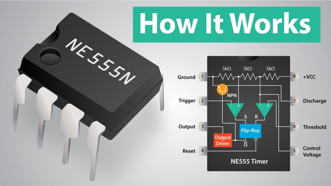
How a 555 Timer IC Works

How 555 timers Work - The Learning Circuit

Off Delay Timer | how to make off delay timer | how to make delay timer | delay timer
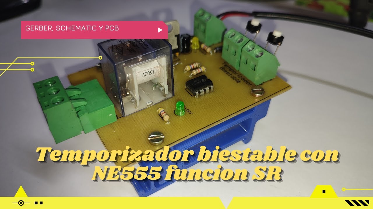
⚡ Proyecto con temporizador biestable con el NE555 y arranque de motor electrico SR con SET y RESET
5.0 / 5 (0 votes)
