PLC Functional Block Diagram basics
Summary
TLDRThis session on PLC programming using Functional Block Diagrams (FBD) introduces participants to the essential concepts and symbols of FBD programming. It covers the five PLC programming methods, emphasizing the graphical nature of FBD. Participants will learn how to connect various blocks, utilize execution control elements, and implement common logical functions like AND, OR, and XOR gates. Practical examples illustrate how to develop functional block diagrams for real-time applications, such as lamp control systems, reinforcing the concepts discussed. Overall, the session equips attendees with the foundational knowledge to create effective PLC control systems.
Takeaways
- 📚 The session focuses on PLC programming using Functional Block Diagrams (FBD), covering structure, symbols, and basic logic functions.
- 🔍 Participants will learn about the five programming methods for PLCs: Ladder Diagram, Functional Block Diagram, Instruction List, Sequential Function Charts, and Structured Text.
- ⚙️ FBD is a graphical language that shows signal and data flows through blocks, allowing for multiple outputs from program instruction units.
- 🔗 Connections in FBD can be horizontal or vertical, but direct wiring of outputs together is forbidden; a boolean block is used to combine outputs instead.
- 🚦 Execution control elements include unconditional and conditional returns, as well as unconditional and conditional jumps, essential for program flow.
- 📦 Function blocks can be standard or user-defined and are represented by square boxes with defined inputs and outputs.
- 🔗 Connectors are used to continue a network on a new line, linking outputs from previous networks effectively.
- 🔤 Common symbols in FBD include AND, OR, XOR, and NOR gates, each with specific output conditions based on their inputs.
- 📝 An example boolean function is provided, illustrating the use of an OR gate and an inverter in FBD.
- 💡 A real-time application example involves controlling a lamp based on pump and pressure conditions, demonstrating practical use of FBD in PLC programming.
Q & A
What is the main focus of the session on PLC programming?
-The session focuses on PLC programming using Functional Block Diagrams (FBD), teaching participants about the structure, basic symbols, and how to write simple logic functions.
What are the five programming methods used for PLC programming according to the IEC 61131-3 standard?
-The five programming methods are Ladder Diagram, Functional Block Diagram, Instruction List, Sequential Function Charts, and Structured Text.
How are inputs and outputs represented in Functional Block Diagrams?
-In Functional Block Diagrams, inputs are represented on the left side of a block, while outputs are on the right side, with the function specified inside the block.
What is the significance of the IEC 61131-3 standard?
-The IEC 61131-3 standard provides guidelines and definitions for programming methods in PLCs, ensuring consistency and interoperability in PLC programming.
What types of connections are used in Functional Block Diagram programming?
-Functional Block Diagrams utilize horizontal and vertical connections to link different blocks or elements. However, wiring multiple outputs together is forbidden.
What is the purpose of the Boolean OR block in FBD?
-The Boolean OR block is used to combine multiple outputs into a single signal, allowing for logical operations where outputs cannot be directly wired together.
Can function blocks in FBD be duplicated or instantiated multiple times?
-Yes, function blocks can be copied and instantiated multiple times within the Functional Block Diagram, allowing for modular and reusable programming.
What are the four main graphical objects in Functional Block Diagram programming?
-The four main graphical objects are connections, execution control elements, function blocks, and connectors, each serving specific purposes in programming.
How is a simple Boolean function like Q = A + B' represented in FBD?
-In FBD, the function Q = A + B' is represented using an OR gate and a NOT gate, where input A is used directly, and input B is inverted before entering the OR function block.
What is an example of a real-time application described in the session?
-An example described is a lamp that is switched on if a pump is running and the pressure is satisfactory, or if a lamp test switch is closed, demonstrating practical use of FBD in control systems.
Outlines

このセクションは有料ユーザー限定です。 アクセスするには、アップグレードをお願いします。
今すぐアップグレードMindmap

このセクションは有料ユーザー限定です。 アクセスするには、アップグレードをお願いします。
今すぐアップグレードKeywords

このセクションは有料ユーザー限定です。 アクセスするには、アップグレードをお願いします。
今すぐアップグレードHighlights

このセクションは有料ユーザー限定です。 アクセスするには、アップグレードをお願いします。
今すぐアップグレードTranscripts

このセクションは有料ユーザー限定です。 アクセスするには、アップグレードをお願いします。
今すぐアップグレード関連動画をさらに表示

Function Block Diagrams | PLC Programming

DASAR PEMOGRAMAN PLC - SIMBOL - SIMBOL DASAR PLC
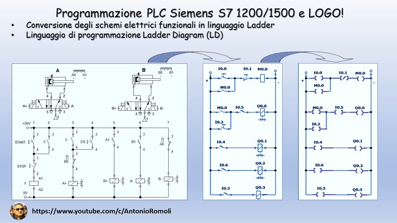
PLC: convertire lo schema elettrico funzionale in linguaggio di programmazione Ladder (Video 1.1)

Ladder Logic Diagrams for PLCs | Industrial Automation
How to Program PLC Using Function Block Diagrams | OpenPLC

1. Tutorial Pemrograman Sekuensial pada PLC
5.0 / 5 (0 votes)
