7.6 Step Response pada Rangkaian RC (1 dari 3)
Summary
TLDRIn this video, the presenter discusses the step response of an RC (resistor-capacitor) circuit. The process begins by explaining how the circuit reacts when a DC source is suddenly applied, using a step function to model the response. Key concepts include the capacitor’s inability to change voltage instantaneously, Kirchhoff’s Current Law (KCL), and the resulting differential equation. The solution to this equation describes the voltage across the capacitor as a function of time. The video also highlights assumptions about the initial conditions of the capacitor and concludes with the expression for the step response in an RC circuit.
Takeaways
- 😀 The video discusses the step response of an RC circuit (resistor-capacitor circuit).
- 😀 The first question addressed is how to test the step response of an RC circuit.
- 😀 The circuit in question includes a voltage source, resistor, capacitor, and a switch.
- 😀 Initially, the switch is open, meaning no current flows through the circuit.
- 😀 When the switch is closed, a sudden voltage or current from the DC source is applied to the circuit, creating a shock or sudden change.
- 😀 The step response of the circuit is modeled using a step function, which was discussed in a previous video.
- 😀 The voltage across the capacitor is chosen as the response of the circuit.
- 😀 Capacitors cannot change voltage suddenly; the voltage across them changes gradually over time.
- 😀 The analysis uses Kirchhoff's Current Law (KCL) to model the circuit, leading to a first-order differential equation describing the capacitor's voltage behavior.
- 😀 The final differential equation is solved to express the voltage as a function of time, showing an exponential approach to a final value.
- 😀 The response of the circuit is referred to as the 'total response' to a step input, and the capacitor initially has a voltage (called V0).
Q & A
What is the step response in an RC circuit?
-The step response in an RC circuit refers to how the circuit reacts when a sudden voltage or current is applied, typically from a DC source. This leads to an exponential voltage change across the capacitor over time.
Why can't the voltage across a capacitor change suddenly?
-The voltage across a capacitor cannot change suddenly because capacitors store charge. Any change in voltage requires time for charge redistribution, resulting in a continuous change rather than an instantaneous one.
What happens to the circuit when the switch is closed in an RC circuit?
-When the switch is closed, the DC voltage source is applied to the circuit, causing a sudden voltage or current change, which leads to the capacitor charging up gradually.
What is the behavior of the capacitor at the moment the switch is closed?
-At the moment the switch is closed, the capacitor’s voltage cannot change instantaneously. The voltage at time zero minus (V₀⁻) and time zero plus (V₀⁺) are the same, indicating a continuous voltage transition.
How is Kirchhoff’s Current Law (KCL) applied to the RC circuit?
-KCL is applied by analyzing the currents entering and leaving a node. In the RC circuit, the current through the resistor and the current through the capacitor sum to zero, which leads to the formulation of the voltage differential equation.
What is the equation that governs the voltage across the capacitor in an RC circuit?
-The voltage across the capacitor in an RC circuit is governed by the differential equation: dV/dt + (V - V_s)/RC = 0, where V is the voltage across the capacitor, V_s is the source voltage, and RC is the time constant.
How is the voltage across the capacitor derived from the differential equation?
-The differential equation is integrated, resulting in the solution: Vc(t) = Vs (1 - e^(-t/RC)), where Vc(t) is the voltage across the capacitor at time t, Vs is the source voltage, and RC is the time constant.
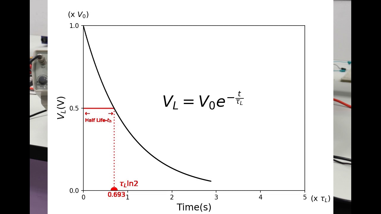
What does the term 'time constant' (RC) represent in the RC circuit?
-The time constant (RC) represents the time it takes for the voltage across the capacitor to change by approximately 63% of its final value. It controls how fast the capacitor charges or discharges.
How does the capacitor voltage behave as time progresses after the switch is closed?
-As time progresses after the switch is closed, the voltage across the capacitor increases exponentially, approaching the source voltage (Vs) over time. The voltage never quite reaches Vs but gets infinitely close.
What is the final voltage across the capacitor once the circuit reaches steady state?
-In the steady state, once the capacitor is fully charged, the voltage across the capacitor will equal the source voltage, Vs. The exponential charge curve flattens, and the capacitor voltage stabilizes at this value.
Outlines

Cette section est réservée aux utilisateurs payants. Améliorez votre compte pour accéder à cette section.
Améliorer maintenantMindmap

Cette section est réservée aux utilisateurs payants. Améliorez votre compte pour accéder à cette section.
Améliorer maintenantKeywords

Cette section est réservée aux utilisateurs payants. Améliorez votre compte pour accéder à cette section.
Améliorer maintenantHighlights

Cette section est réservée aux utilisateurs payants. Améliorez votre compte pour accéder à cette section.
Améliorer maintenantTranscripts

Cette section est réservée aux utilisateurs payants. Améliorez votre compte pour accéder à cette section.
Améliorer maintenantVoir Plus de Vidéos Connexes

35 DC Tutorial para obtener la solución General de Circuitos RC con Condiciones Iniciales.
RC and RL Circuits
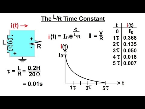
Electrical Engineering: Ch 8: RC & RL Circuits (11 of 43) The L/R Time Constant
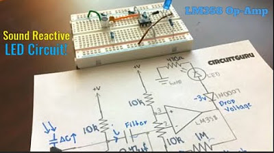
Sound Reactive LED Circuit Using LM358 Op-Amp and Mic

7.6 Step Response pada Rangkaian RC (3 dari 3)
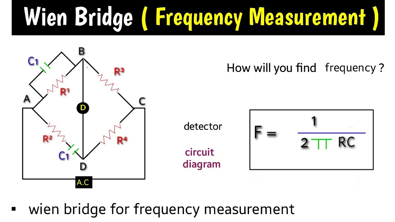
wien bridge |frequency measurement by Wien bridge | Wiens bridge in hindi | wien's bridge | formula
5.0 / 5 (0 votes)
