Understanding Logic Gates

Spanning Tree
15 Jun 202007:27

Summary

TLDRThis script delves into the fundamental concepts of computer logic, starting from the binary system formed by transistors acting as switches represented by 0s and 1s. It explains the role of logic gates as the building blocks of computer circuits, detailing the functions of NOT, AND, OR, NAND, NOR, XOR, and XNOR gates. The script illustrates how these simple gates can be combined to create complex calculations, forming the basis of all data representation and computational processes in computers.

Takeaways

  • 🌟 Computers are made up of billions of tiny units called transistors, which can act as switches.
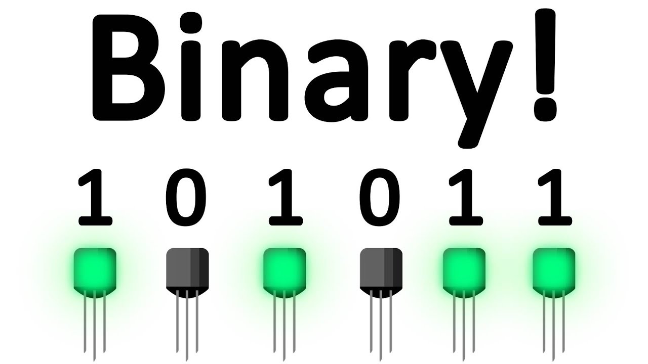
  • 🔢 The binary number system, composed of 0s and 1s, is the fundamental language of computers.
  • 🛠️ Logic gates are the building blocks of computer circuits, processing inputs into outputs based on logical rules.
  • 🔄 The NOT gate is a simple logic gate that inverts its input, turning 0 into 1 and vice versa.
  • 📊 A truth table is a method to represent the logical rules of a gate, showing all possible input-output combinations.
  • ⚙️ The AND gate outputs 1 only when both inputs are 1, otherwise, it outputs 0.
  • 🔄 The OR gate outputs 1 if at least one of the inputs is 1, otherwise, it outputs 0.
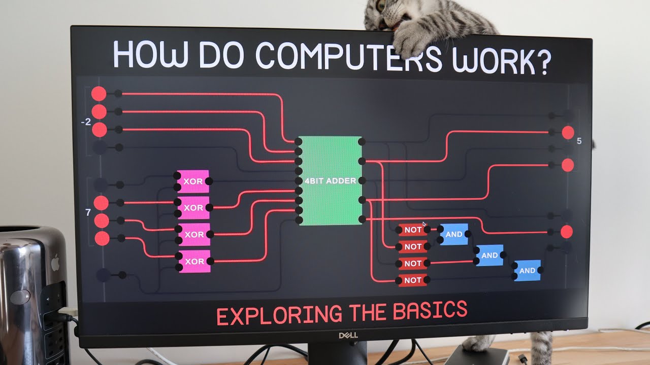
  • 🔀 Complex calculations can be achieved by combining simple logic gates, such as using an AND gate followed by a NOT gate.
  • 🚫 The NAND gate is an AND gate followed by a NOT gate, inverting the output of the AND operation.
  • 🔄 The NOR gate is an OR gate followed by a NOT gate, outputting 1 only when both inputs are 0.
  • 🔒 The XOR (Exclusive OR) gate outputs 1 when exactly one of its inputs is 1, otherwise, it outputs 0.
  • 🔒 The XNOR (Exclusive NOR) gate does the opposite of XOR, outputting 1 when both inputs are the same.

Q & A

  • What are the basic units inside a computer that act like small light switches?

    -The basic units inside a computer are called transistors, which can be turned on or off to perform various functions.

  • What is the number system formed by the zeros and ones that represent the state of the switches?

    -The number system formed by the zeros and ones is called binary, which is the fundamental language of computers.

  • What is the purpose of logic gates in computer circuits?

    -Logic gates are the building blocks of computer circuits that accept inputs and produce outputs according to a set of logical rules.

  • How does the NOT gate function in terms of input and output?

    -The NOT gate takes a single input of either 0 or 1 and inverts it, so if the input is 1, it outputs 0, and if the input is 0, it outputs 1.

  • What is a truth table and how is it used?

    -A truth table is a way of writing down the rules for logical formulas, showing all possible inputs and their corresponding outputs for a given logic gate.

  • How does the AND gate determine its output based on its inputs?

    -The AND gate outputs a 1 only when both of its inputs are 1. In all other cases, it outputs a 0.

  • What is the function of the OR gate in terms of its inputs and output?

    -The OR gate outputs a 1 when either of its inputs is 1. It only outputs 0 when both inputs are 0.

  • What happens when two inputs are passed into an AND gate and then the output is passed into a NOT gate?

    -If both inputs are 0, the AND gate outputs 0, and the NOT gate inverts it to 1. If both inputs are 1, the AND gate outputs 1, and the NOT gate inverts it to 0.

  • What is the purpose of the NAND gate and how is its truth table different from the AND gate?

    -The NAND gate is equivalent to an AND gate followed by a NOT gate. Its truth table is the same as the AND gate, but all outputs are inverted.

  • What is the logical representation for the condition where exactly one of two inputs is a 1?

    -The logical representation for exactly one input being a 1 is A OR B AND NOT (A AND B), which means one must be 1, but not both.

  • What is the function of the XOR gate and how does it differ from the OR gate?

    -The XOR gate outputs a 1 when exactly one of its inputs is a 1, unlike the OR gate, which outputs a 1 if either or both inputs are 1.

  • What is the exclusive NOR gate and how does it function in comparison to the exclusive OR gate?

    -The exclusive NOR gate is the inverse of the exclusive OR gate. It outputs a 1 when both inputs are the same (both 0s or both 1s), whereas the exclusive OR gate outputs a 1 when the inputs are different.

  • How can a combination of simple logic gates perform complex calculations?

    -By combining simple logic gates like NOT, AND, OR, NAND, NOR, and XOR, we can construct complex circuits capable of performing all the calculations that computers do every day.

Outlines

00:00

🌟 Fundamentals of Computer Logic and Binary System

This paragraph introduces the basic building blocks of computer systems: transistors, which function as tiny switches that can be either on or off. These switches form the binary number system, represented by 0s and 1s, which is the fundamental language of computers. The paragraph explains how computer scientists use these binary digits to perform a variety of tasks, including calculations, document creation, image viewing, and web browsing. It also delves into the concept of logic gates, which are the foundational components of computer circuits. Logic gates accept inputs and produce outputs based on logical rules. The paragraph provides examples of simple logic gates like NOT, AND, and OR, explaining their functions and the truth tables that represent their logical rules. It further discusses how these gates can be combined to form more complex calculations, such as using an AND gate followed by a NOT gate to create a NAND gate, which inverts the output of the AND gate.

05:01

🔍 Advanced Logic Gates and Problem Solving

The second paragraph explores more complex logic gates and their applications in solving specific computational problems. It starts by explaining the NOR gate, which inverts the output of an OR gate, and the use of logic gates to solve the problem of determining if exactly one of two inputs is a 1. This is achieved through the use of an exclusive OR (XOR) gate, which outputs a 1 only when the inputs are different. The paragraph also introduces the exclusive NOR (XNOR) gate, which outputs a 1 when both inputs are the same. The summary emphasizes the ability to combine these simple logical gates to create more sophisticated systems capable of performing all the complex calculations and data representation tasks that modern computers accomplish daily.

Mindmap

Keywords

💡Transistors

Transistors are semiconductor devices that can amplify or switch electronic signals and electrical power. They are the fundamental building blocks of modern electronic devices. In the context of the video, transistors act as tiny switches within a computer, with the ability to be turned on or off, representing the binary digits 1 and 0, which form the basis of computer logic and operations.

💡Binary System

The binary system is a number system that uses only two symbols, typically 0 and 1, to represent all possible values. It is the fundamental language of computers, as it allows for the representation of complex information in a simple, on/off state. The video explains how zeros and ones are used to perform various computer functions, emphasizing the binary system's critical role in digital computation.

💡Logic Gates

Logic gates are the building blocks of digital circuits, processing input signals and producing output signals based on a logical function. The video discusses various logic gates such as AND, OR, NOT, NAND, NOR, and XOR, which are essential for creating complex computational systems. These gates are the core of computer circuits and are used to process information through a set of logical rules.

💡NOT Gate

The NOT gate, also known as an inverter, is a basic logic gate with a single input and a single output. It inverts the input signal; if the input is 1, it outputs 0, and vice versa. The video uses the NOT gate to illustrate the concept of inverting an input, which is a common operation in digital circuits and is fundamental to the operation of more complex logic gates.

💡AND Gate

The AND gate is a logic gate that takes two inputs and outputs a 1 only when both inputs are 1. It is used to represent the logical conjunction of two conditions. In the video, the AND gate is explained as a fundamental component in digital circuits, where it helps in performing calculations that require both conditions to be true.

💡OR Gate

The OR gate is another basic logic gate that outputs a 1 if at least one of its inputs is 1. It represents the logical disjunction, meaning that if either or both inputs are true, the output is true. The video script uses the OR gate to demonstrate how multiple bits of information can be processed to yield a single result.

💡NAND Gate

The NAND gate is a logic gate that performs an AND operation on its inputs and then negates the result. It outputs a 0 only when both inputs are 1, and a 1 in all other cases. The video explains the NAND gate as a combination of an AND gate followed by a NOT gate, highlighting its use in inverting the result of an AND operation.

💡NOR Gate

The NOR gate is a logic gate that outputs a 1 only when both inputs are 0. It is the inverse of the OR gate, meaning it outputs the opposite of what an OR gate would. The video script mentions the NOR gate as an example of how logic gates can be inverted to perform different logical operations.

💡XOR Gate

The XOR gate, or exclusive OR gate, outputs a 1 if the inputs are different, meaning one is 1 and the other is 0. It outputs a 0 if both inputs are the same. The video script explains the XOR gate as a specific logic gate used to determine when exactly one of the inputs is true, which is a common requirement in various computational tasks.

💡XNOR Gate

The XNOR gate, or exclusive NOR gate, is the inverse of the XOR gate. It outputs a 1 when both inputs are the same (both 0 or both 1) and outputs a 0 when the inputs differ. The video script briefly mentions the XNOR gate to complete the set of basic logic gates, showing how it can be used to perform the opposite operation of the XOR gate.

💡Truth Table

A truth table is a mathematical table used in logic to describe the output of a logical formula given all its possible inputs. In the video, truth tables are used to illustrate the rules followed by logic gates, such as the NOT, AND, OR, NAND, NOR, XOR, and XNOR gates. They provide a clear and concise way to understand the behavior of these gates for different combinations of inputs.

Highlights

Computers operate on a binary system using zeros and ones to represent information.

Transistors act as tiny light switches, forming the basis of computer logic.

Logic gates are the building blocks of computer circuits, processing inputs into outputs.

The NOT gate inverts the input, representing a fundamental logic operation.

Truth tables are used to illustrate the rules of logical operations.

The AND gate outputs a 1 only when both inputs are 1, showcasing basic logic gate functionality.

The OR gate outputs a 1 when at least one input is 1, expanding on basic logic operations.

Combining logic gates allows for more complex calculations and operations.

The NAND gate is equivalent to an AND gate followed by a NOT gate, inverting the result.

The NOR gate inverts the output of an OR gate, providing another fundamental logic operation.

The EXCLUSIVE OR (XOR) gate outputs a 1 when exactly one input is 1, addressing a specific logical condition.

The EXCLUSIVE NOR (XNOR) gate outputs a 1 when both inputs are the same, complementing the XOR gate.

Logic gates can be combined to solve complex logical problems, such as determining if exactly one input is 1.

Computers use these basic logic gates to represent and process all types of data and calculations.

Understanding the binary system and logic gates is crucial for the foundations of computer science.

The simplicity of individual logic gates enables the creation of sophisticated computer systems.

This series aims to explore the progression from basic to advanced computer logic systems.

Transcripts

play00:00

inside your computer are billions of

play00:02

units called transistors these

play00:04

transistors serve a variety of purposes

play00:06

but they commonly act as a sort of very

play00:09

small light switch each switch can be

play00:12

turned on or turned off computer

play00:15

scientists will often represent a switch

play00:17

that's turned on with the number one and

play00:19

a switch that's turned off with the

play00:22

number zero these zeros and ones form a

play00:25

number system called binary and it's the

play00:27

fundamental language of computers from

play00:30

just these zeros and ones we end up with

play00:32

computers that can perform calculations

play00:34

create documents view images browse the

play00:37

web and more how does that happen in

play00:40

this series we'll explore the

play00:42

foundations of computer logic starting

play00:44

from the fundamentals and building our

play00:46

way to more and more sophisticated

play00:48

systems

play00:50

using these switches our computers can

play00:53

store information each switch stores a

play00:56

single bit of information a 0 or a 1 but

play01:00

computers don't just store information

play01:02

they process it transforming inputs into

play01:06

outputs

play01:07

that's where logic gates come in logic

play01:11

gates are the building blocks of

play01:12

computer circuits they accept input and

play01:15

produce output according to a set of

play01:18

logical rules one of the simplest logic

play01:22

gates is the not gate represented

play01:25

graphically here the not gate takes a

play01:27

single input either a 0 or a 1 and

play01:30

inverts it so that the output is the

play01:33

opposite of whatever the input is if the

play01:37

input is a 1 then the not gate outputs a

play01:40

0 if the input is a 0 then the not gate

play01:43

outputs a 1 to represent the logical

play01:47

rule this gate obeys we can draw a truth

play01:50

table which is just a way of writing

play01:52

down the rules for some logical formula

play01:55

this table says that if the input is 0

play01:57

then the output is 1 and if the input is

play02:00

1 the output is 0 often though our

play02:05

computers need to be able to perform

play02:06

calculations not just on a single bit of

play02:09

information but on multiple bits of

play02:12

information the and gate shown here for

play02:15

example is a logic gate that takes two

play02:18

inputs instead of one let's call these

play02:21

two inputs a and B as the name might

play02:24

suggest the and gate will output a 1

play02:27

when both a and B are ones but in all

play02:31

other cases and will output a 0 we can

play02:36

construct a truth table here too

play02:38

this truth table is a bit bigger since

play02:41

with two inputs there are more

play02:42

possibilities to consider if a and B are

play02:45

0 the output is 0 if a is 0 and B is 1

play02:50

the output is 0 if a is 1 and B is 0 the

play02:54

output is still 0 and only when both a

play02:57

and B are ones is the output a 1

play03:02

the or gate meanwhile is also a logic

play03:05

gate that takes two inputs this gate

play03:09

outputs a 1 when a is a 1 or when B is a

play03:12

1 so if both inputs are 0 the or gate

play03:17

outputs 0 but if either of the inputs is

play03:20

a 1 or both inputs are a 1 then the

play03:23

output of the or gate is also going to

play03:26

be a 1 these logic gates on their own

play03:29

follow fairly simple rules but they can

play03:33

combine with each other to form more

play03:34

complex calculations imagine what would

play03:37

happen if for example we took two inputs

play03:40

pass them into a NAND gate and then

play03:43

passed that output into a not gate what

play03:46

would happen if both inputs are 0 the

play03:50

and gate will output a 0 and the knot

play03:53

will turn that 0 into a 1 if only one of

play03:57

the inputs is a 0 nothing changes but if

play04:00

both inputs are 1 the and gate will

play04:03

output a 1 and the knot will turn that

play04:06

one into a 0 in other words this circuit

play04:10

appears to do the opposite of whatever

play04:12

the and gate on its own would do it

play04:16

turns out that inverting the result of

play04:18

an and calculation is such a common

play04:20

operation that it has its own logic gate

play04:23

the NAND gate this gate is equivalent to

play04:26

an and followed by a naught so if the

play04:29

and truth table looks like this then the

play04:33

NAND truth table is identical except all

play04:36

of the outputs are inverted whenever and

play04:39

when output is 0 mand outputs a 1

play04:42

whenever and when I open a 1-man outputs

play04:45

a 0

play04:47

as you might guess if there's a logic

play04:49

gate to take the opposite of a NAND gate

play04:51

there is also a logic gate that takes

play04:54

the opposite of an or gate this is the

play04:57

nor gate when both inputs are zero or

play05:00

would normally output a zero to so the

play05:04

nor gate will flip that and output a 1

play05:06

in all other cases at least one of the

play05:10

inputs is 1 so or would output a 1 and

play05:13

so the nor gate will output a 0 instead

play05:17

let's now use these gates to solve a

play05:20

sample problem given two inputs a and B

play05:23

we'd like to calculate whether exactly

play05:26

one of them is a 1 well what does it

play05:29

mean logically for exactly one of these

play05:31

two inputs to be a 1 well it means that

play05:34

either A or B must be a 1 but it also

play05:38

means they can't both be a 1 so

play05:42

logically we might represent this as a

play05:44

or B and not a and B to mean that one of

play05:50

the two must be a 1 but both can't be a

play05:54

1

play05:55

we could create a circuit to perform

play05:58

this calculation too but this circuit is

play06:00

starting to look fairly complex so once

play06:04

again there's a logic gate to solve this

play06:06

problem precisely the exclusive or gate

play06:09

outputs a 1 when exactly one of its

play06:13

inputs is a 1 so if only a is 1 or only

play06:17

B is 1 then the output of exclusive-or

play06:20

is 1 but otherwise if both inputs have

play06:25

the same value both zeros or both ones

play06:28

then the output is 0

play06:31

and just for completeness sake there's

play06:34

also a gate for inverting the exclusive

play06:36

or gate the exclusive nor gate this gate

play06:40

does the opposite of what exclusive or

play06:43

does while exclusive or will output a

play06:46

one when the two inputs are different

play06:48

from each other exclusive nor will

play06:51

output a one when the two inputs are the

play06:53

same both zeros or both ones

play06:58

these illogical gates not and/or manned

play07:02

nor exclusive or and exclusive nor make

play07:06

up the foundation of computation in

play07:08

computers by combining just these few

play07:11

logical gates each of which obey is a

play07:13

relatively simple logical rule we can

play07:16

construct computers that can represent

play07:18

all of the data and perform all of the

play07:21

complex calculations that our computers

play07:23

do every day

play07:26

you

Rate This

5.0 / 5 (0 votes)

Étiquettes Connexes
Binary SystemLogic GatesComputer ScienceTransistorsAND GateOR GateNOT GateNAND GateNOR GateXOR GateExclusive NOR
Besoin d'un résumé en anglais ?