Using Diodes as Clippers or Clampers | Intermediate Electronics
Summary
TLDRIn this educational video, the presenter explores the concepts of clippers and clampers in electronics, using a simple circuit setup with a waveform generator and oscilloscope. They demonstrate various types of clippers, including negative and positive series clippers, and how they clip the input signal differently. The video also covers biased series clippers and their behavior with DC offsets. Parallel clippers are shown, highlighting the diode's role in determining the load voltage. Finally, a clamper circuit is explained, illustrating how it shifts the entire waveform's voltage. The presenter encourages hands-on learning and refers viewers to a detailed written tutorial by Harold for further understanding.
Takeaways
- 🔬 The tutorial focuses on demonstrating clippers and clampers in electronic circuits.
- 📚 Harold's written tutorial on CircaBred.com is recommended for detailed mathematical explanations.
- 🔌 The setup includes a simple circuit connected to a waveform generator and an oscilloscope.
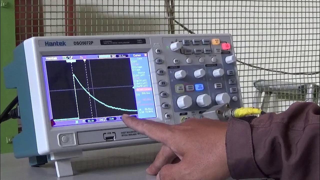
- 📈 The oscilloscope displays the output of the generator and the effect across the load with different circuits.
- ⚡ A negative series clipper is shown first, which clips the positive part of the input signal, similar to a half-wave rectifier.
- 🔄 Flipping the diode demonstrates a positive series clipper, which clips the negative part of the input signal.
- 🔌 Biased series clippers are shown with a DC offset, affecting the clipping level of the input signal.
- 🔗 Parallel clippers are introduced, where the diode is in parallel with the load, affecting the voltage across the load based on diode bias.
- 🔋 A clamper circuit is demonstrated, which uses a capacitor and a diode to shift the entire waveform up or down in voltage.
- 🎥 The video emphasizes the importance of hands-on experience and practical demonstration for better understanding of these concepts.
Q & A
What is the main topic of the tutorial video?
-The main topic of the tutorial video is about clippers and clampers in electronic circuits.
Who created the written tutorial mentioned in the video?
-Harold created the written tutorial on clippers and clampers.
What is the purpose of using a waveform generator and an oscilloscope in the demonstration?
-The purpose of using a waveform generator and an oscilloscope is to show the output of the generator and what happens across the load with different circuits.
What is a negative series clipper and how is it demonstrated in the video?
-A negative series clipper is a circuit that clips the positive part of an input signal, leaving only the negative part. It is demonstrated by showing the output on an oscilloscope after the signal passes through a diode.
How does a positive series clipper differ from a negative series clipper?
-A positive series clipper is set up by reversing the diode in the circuit, which results in clipping the negative part of the input signal, leaving only the positive part.
What is the effect of bias on a series clipper circuit?
-Biasing a series clipper circuit shifts the entire waveform up or down. A positive bias shifts the waveform up, clipping less of the negative part, while a negative bias shifts it down, clipping less of the positive part.
What is the role of the diode in a parallel clipper circuit?
-In a parallel clipper circuit, the diode allows current to flow through the load only when it is reverse-biased, effectively clipping the signal when the diode is forward-biased.
How does the bias affect the output of a parallel clipper?
-Biasing a parallel clipper affects the output by shifting the point at which the diode starts to conduct. A positive bias reduces the voltage across the load during forward bias, while a negative bias increases it.
What is a clamper circuit and how does it differ from a clipper?
-A clamper circuit is designed to shift the entire waveform up or down without clipping it. It differs from a clipper in that it does not remove parts of the waveform but rather shifts the entire waveform to a new voltage level.
What components are typically used in a clamper circuit?
-A clamper circuit typically uses a diode, a capacitor, and a resistor. The capacitor is in series with the diode, and the resistor is in parallel with them.
Why does the clamper circuit not provide a free increase in voltage?
-The clamper circuit does not provide a free increase in voltage because it shifts the entire waveform up or down without adding or removing energy from the circuit; it merely redistributes the existing voltage levels.
Outlines

Dieser Bereich ist nur für Premium-Benutzer verfügbar. Bitte führen Sie ein Upgrade durch, um auf diesen Abschnitt zuzugreifen.
Upgrade durchführenMindmap

Dieser Bereich ist nur für Premium-Benutzer verfügbar. Bitte führen Sie ein Upgrade durch, um auf diesen Abschnitt zuzugreifen.
Upgrade durchführenKeywords

Dieser Bereich ist nur für Premium-Benutzer verfügbar. Bitte führen Sie ein Upgrade durch, um auf diesen Abschnitt zuzugreifen.
Upgrade durchführenHighlights

Dieser Bereich ist nur für Premium-Benutzer verfügbar. Bitte führen Sie ein Upgrade durch, um auf diesen Abschnitt zuzugreifen.
Upgrade durchführenTranscripts

Dieser Bereich ist nur für Premium-Benutzer verfügbar. Bitte führen Sie ein Upgrade durch, um auf diesen Abschnitt zuzugreifen.
Upgrade durchführen5.0 / 5 (0 votes)


