BJT: Collector Feedback Bias Explained
Summary
TLDRThis video from the All About Electronics YouTube channel explores the Collector Feedback Biasing configuration of a Bipolar Junction Transistor (BJT). It explains how this configuration uses negative feedback from the collector to the base through resistor Rb to stabilize the operating point against external parameter changes like temperature. The script delves into DC analysis, deriving expressions for base current, collector current, and voltage Vce. It also discusses the impact of β variations on the operating point and suggests that for utmost stability, a voltage divider configuration may be preferable. The video concludes with an invitation for viewers to engage with the content through comments and subscriptions.
Takeaways
- 📚 The video discusses the Collector Feedback Biasing configuration of a Bipolar Junction Transistor (BJT).
- 🔄 The purpose of this biasing configuration is to stabilize the operating point of the BJT through negative feedback from the collector to the base terminal via resistor Rb.
- 🌡️ The circuit is designed to minimize changes in the operating point due to external parameters like temperature.
- 🔌 For DC analysis, capacitors in the circuit are considered as open circuits.
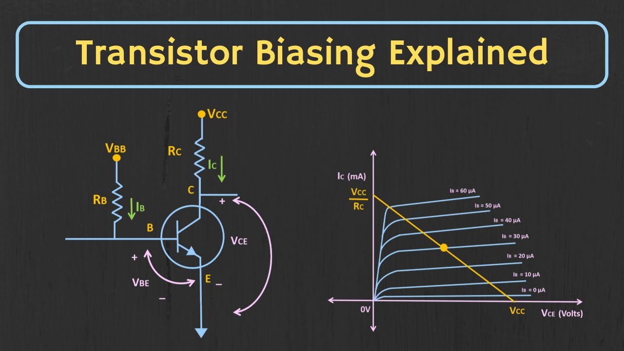
- 🛠️ The DC analysis involves marking currents and applying Kirchhoff's Voltage Law (KVL) to find expressions for base current (Ib), collector current (Ic), and voltage Vce.
- ⚖️ The collector current Ic is approximately equal to the current through resistor Rc, and can be considered much larger than the base current Ib when β is high.
- 🔢 The base current Ib can be calculated using the formula: Ib = (Vcc - Vbe) / (Rb + β*Rc).
- 🔗 The collector current Ic is directly proportional to the base current Ib, with the relationship Ic = β*Ib.
- 📉 The voltage Vce across the collector and emitter can be found using the formula: Vce = Vcc - Ic*Rc.
- 🔄 An improved stability can be achieved by adding an emitter resistor, creating a collector and emitter feedback bias configuration.
- 🔍 The operating point's sensitivity to changes in β is demonstrated through an example, showing variations in Ic and Vce with different β values.
- 📉 The example illustrates that even with collector feedback, the operating point can still vary significantly with changes in β.
- ⚠️ The condition for the base current Ib to be independent of β is when Rb is much less than β*(Rc + Re), which is not always practical for BJT operation.
- 📉 The video concludes that while collector feedback biasing offers some improvement in stability, it is not as stable as a voltage divider configuration for very stable operating points.
Q & A
What is the main purpose of the collector feedback biasing configuration in a BJT?
-The main purpose of the collector feedback biasing configuration in a BJT is to stabilize the operating point through negative feedback, minimizing changes in the operating point due to external parameter variations such as temperature.
How does the collector feedback biasing configuration provide negative feedback in a BJT?
-The collector feedback biasing configuration provides negative feedback by connecting a resistor (Rb) from the collector to the base terminal, which helps to stabilize the operating point by reducing the base current if the collector current increases, due to temperature or other factors.
What is the significance of the resistor Rc in the collector feedback biasing configuration?
-The resistor Rc is significant in the collector feedback biasing configuration as it creates a voltage drop when the collector current (Ic) flows through it. This voltage drop affects the collector voltage (Vc), which in turn influences the base current (Ib) and helps in stabilizing the operating point.
How does an increase in temperature affect the collector current Ic and the base current Ib in the collector feedback biasing configuration?
-An increase in temperature can cause the collector current Ic to increase, which leads to an increased voltage drop across the resistor Rc, reducing the collector voltage (Vc). As a result, the base current Ib will decrease, which in turn reduces the collector current Ic, due to the relationship Ic = β * Ib.
What is the role of the KVL (Kirchhoff's Voltage Law) in the DC analysis of the collector feedback biasing configuration?
-The KVL is used in the DC analysis to derive the expressions for the base current (Ib), collector current (Ic), and the voltage across the collector-emitter (Vce). It helps in understanding how the voltages and currents are related in the circuit and how they contribute to the stabilization of the operating point.
What is the expression for the base current Ib in the collector feedback biasing configuration?
-The expression for the base current Ib in the collector feedback biasing configuration is Ib = (Vcc - Vbe) / (Rb + β * Rc), where Vcc is the supply voltage, Vbe is the base-emitter voltage, Rb is the base resistor, β is the current gain, and Rc is the collector resistor.
How does the addition of an emitter resistor improve the stability of the collector feedback biasing configuration?
-The addition of an emitter resistor (Re) provides additional negative feedback to the circuit, which helps to further stabilize the operating point. The emitter resistor creates a voltage drop that affects the base current, enhancing the circuit's ability to maintain a stable operating point despite variations in external parameters.
What is the condition for the base current Ib to become independent of the value of β in the collector feedback biasing configuration?
-The condition for the base current Ib to become independent of the value of β is when Rb is much less than β * (Rc + Re). In this case, the base current Ib can be approximated as (Vcc - Vbe) / β * (Rc + Re), and the collector current Ic becomes independent of β variations.
What are the limitations of the collector feedback biasing configuration in terms of stability?
-While the collector feedback biasing configuration provides improved stability over fixed bias configurations, it still experiences variations in the operating point due to changes in external parameters. The stability is not as high as that provided by a voltage divider configuration, which is why it is widely used for applications requiring a very stable operating point.
How does the change in the value of β affect the operating point of the BJT in the collector feedback biasing configuration?
-A change in the value of β affects the operating point by altering the base current Ib and consequently the collector current Ic. An increase in β can lead to an increase in Ic and a decrease in Vce, as demonstrated in the example provided in the script. However, the impact of β variations can be mitigated by carefully selecting resistor values.
Outlines

هذا القسم متوفر فقط للمشتركين. يرجى الترقية للوصول إلى هذه الميزة.
قم بالترقية الآنMindmap

هذا القسم متوفر فقط للمشتركين. يرجى الترقية للوصول إلى هذه الميزة.
قم بالترقية الآنKeywords

هذا القسم متوفر فقط للمشتركين. يرجى الترقية للوصول إلى هذه الميزة.
قم بالترقية الآنHighlights

هذا القسم متوفر فقط للمشتركين. يرجى الترقية للوصول إلى هذه الميزة.
قم بالترقية الآنTranscripts

هذا القسم متوفر فقط للمشتركين. يرجى الترقية للوصول إلى هذه الميزة.
قم بالترقية الآنتصفح المزيد من مقاطع الفيديو ذات الصلة

Transistor Introduction (Bipolar Transistors & its Biasing) Basic Electronics
Transistor Biasing: What is Q-point? What is Load Line? Fixed Bias Configuration Explained
Introduction to Bipolar Junction Transistors (BJT)
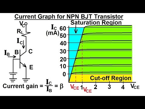
Electrical Engineering: Ch 3: Circuit Analysis (28 of 37) Current Graph for NPN BJT Transistor
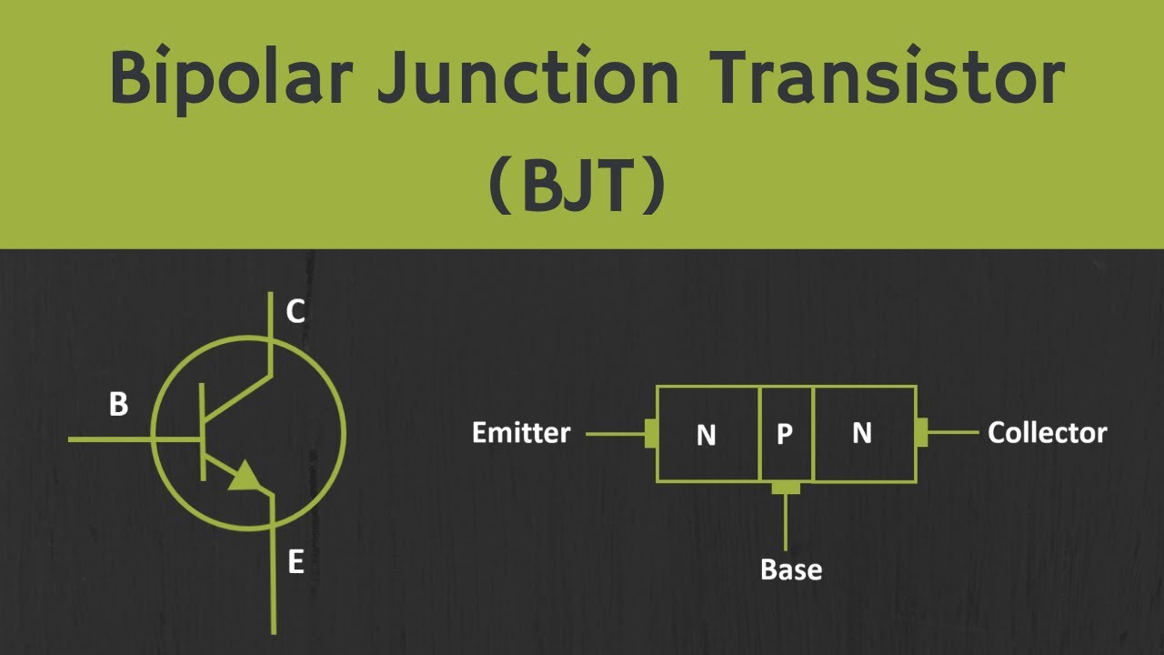
Introduction to Bipolar Junction Transistor (BJT)

CEK KOMPONEN PART 2 , MENGUKUR TRANSISTOR BJT
5.0 / 5 (0 votes)
