Straight-Through and Crossover Cables - N10-008 CompTIA Network+ : 2.3
Summary
TLDRThe video explains the differences between straight-through and crossover Ethernet cables, commonly used in network connections. It covers how straight-through cables are typically used to connect workstations to network switches, and crossover cables are used when connecting similar devices like two switches or two computers. The script details how data flows in 10/100-Megabit and Gigabit Ethernet, highlighting the role of pins and Auto-MDI-X technology, which automatically determines if a crossover is needed. It also debunks misconceptions about cable wiring standards for crossover cables in gigabit networks.
Takeaways
- 🔌 Ethernet straight-through cables connect identical pins on both ends (e.g., pin 1 to pin 1, pin 2 to pin 2).
- 🖥️ Straight-through cables are commonly used to connect devices like workstations to network switches.
- 📡 For 10BASE-T and 100BASE-T Ethernet, only two pairs of wires are used (pins 1, 2, 3, and 6).
- 💡 The media-dependent interface (MDI) is responsible for transmitting data, while the MDI-X on the switch handles receiving.
- 🔄 In gigabit (1000BASE-T) Ethernet, all four pairs of wires are used, and each wire can both transmit and receive data.
- 🔀 A crossover cable is needed when connecting two MDI devices or two MDI-X devices (e.g., workstation to workstation or switch to switch).
- 🤖 Auto-MDI-X is a feature in modern Ethernet devices that automatically detects whether a crossover cable is needed and adjusts accordingly.
- 📊 In gigabit Ethernet, the concept of a crossover cable is different, with all eight wires crossing over, not just two pairs.
- 🛠️ Crossover cables for gigabit Ethernet are not simply a combination of TIA 568A on one side and 568B on the other.
- 🧠 Use a straight-through cable for different devices (e.g., workstation to switch), but use a crossover cable for like devices (e.g., switch to switch).
Q & A
What is a straight-through cable, and where is it commonly used?
-A straight-through cable connects the same pin numbers on both ends (pin 1 to pin 1, pin 2 to pin 2, etc.). It's commonly used to connect workstations to network devices like switches.
What is a patch cable, and how does it relate to straight-through cables?
-A patch cable is a type of straight-through cable used inside wiring closets to connect a patch panel to an Ethernet switch.
Which pairs of wires are used in 10BASE-T and 100BASE-T Ethernet straight-through cables?
-In 10BASE-T and 100BASE-T Ethernet straight-through cables, only two pairs of wires (pins 1, 2, 3, and 6) are used for transmitting and receiving data.
What is an MDI, and what is its role in Ethernet networking?
-MDI stands for Media-Dependent Interface. It refers to the network interface card (NIC) in a computer, responsible for transmitting and receiving data over Ethernet cables.
How do the pin configurations of MDI and MDI-X differ?
-MDI uses pin 1 for transmit and pin 3 for receive, while MDI-X (typically in switches) uses pin 1 for receive and pin 3 for transmit, ensuring proper communication between devices.
Why do gigabit Ethernet (1000BASE-T) cables differ from 10/100 Mbps Ethernet cables?
-In gigabit Ethernet, all four wire pairs are used for both transmitting and receiving data simultaneously, unlike 10/100 Mbps Ethernet, where only two pairs are used.
When should a crossover cable be used instead of a straight-through cable?
-A crossover cable is used when connecting two devices of the same type, like two workstations or two switches. For different types (e.g., workstation to switch), a straight-through cable is used.
What is Auto-MDI-X, and how does it simplify network connections?
-Auto-MDI-X is a feature in modern Ethernet devices that automatically detects the need for a crossover cable and adjusts the connection internally, eliminating the need for a physical crossover cable.
Why is the assumption that crossover cables use 568A on one side and 568B on the other incorrect?
-This assumption is a misnomer, especially in gigabit Ethernet (1000BASE-T). The crossover configuration is based on the IEEE 802.3 Ethernet standard, which does not follow the 568A and 568B color coding for crossover cables.
What type of cable should be used when connecting a router to a switch?
-A straight-through cable should be used when connecting a router to a switch because they are different device types (MDI to MDI-X).
Outlines

هذا القسم متوفر فقط للمشتركين. يرجى الترقية للوصول إلى هذه الميزة.
قم بالترقية الآنMindmap

هذا القسم متوفر فقط للمشتركين. يرجى الترقية للوصول إلى هذه الميزة.
قم بالترقية الآنKeywords

هذا القسم متوفر فقط للمشتركين. يرجى الترقية للوصول إلى هذه الميزة.
قم بالترقية الآنHighlights

هذا القسم متوفر فقط للمشتركين. يرجى الترقية للوصول إلى هذه الميزة.
قم بالترقية الآنTranscripts

هذا القسم متوفر فقط للمشتركين. يرجى الترقية للوصول إلى هذه الميزة.
قم بالترقية الآنتصفح المزيد من مقاطع الفيديو ذات الصلة

568A and 568B Colors - CompTIA A+ 220-1101 - 3.1

T568A vs T568B - what's the difference and how to test patch leads.
Free CCNA | Interfaces and Cables | Day 2 | CCNA 200-301 Complete Course
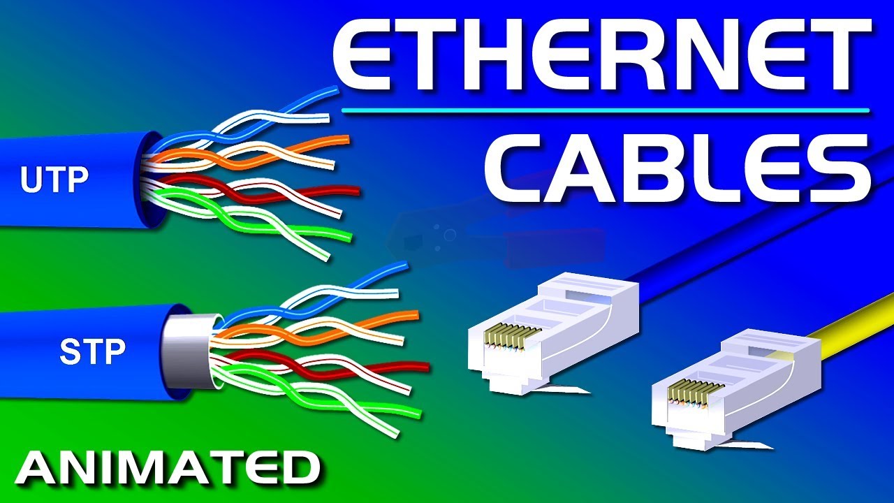
Ethernet Cables, UTP vs STP, Straight vs Crossover, CAT 5,5e,6,7,8 Network Cables
Proxy Server Configuration Using Cisco Packet Tracer in Hindi
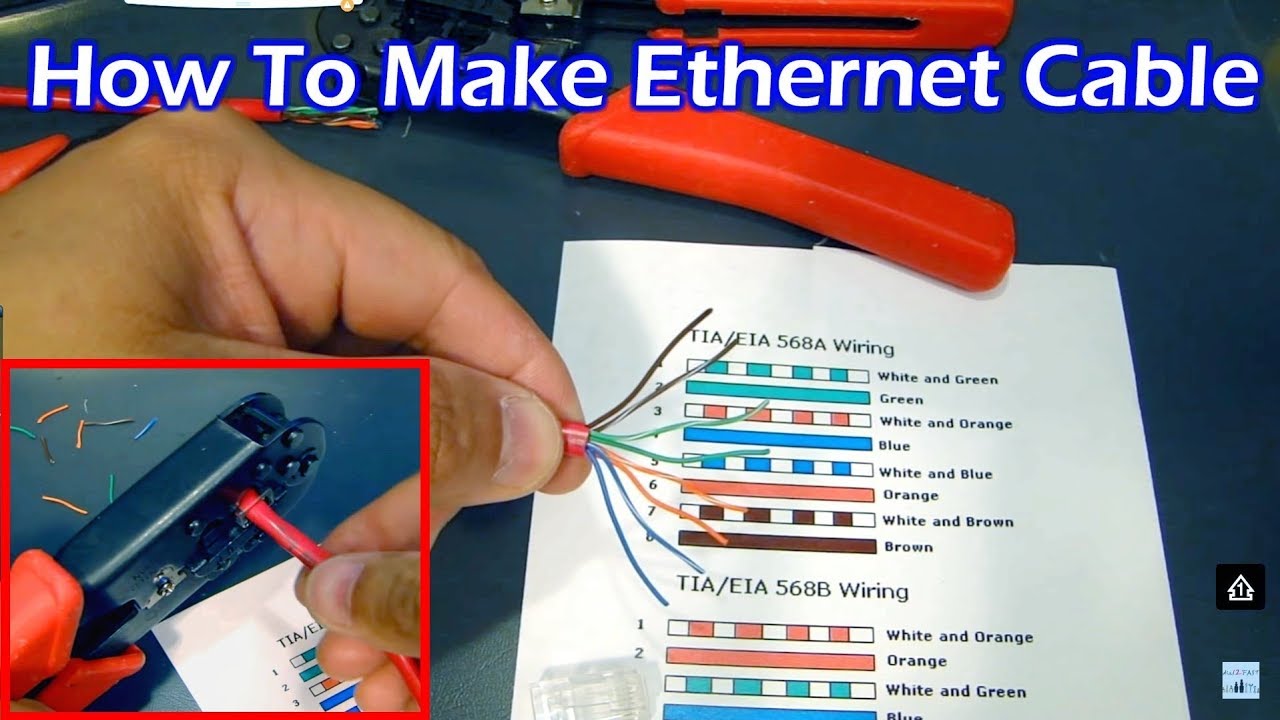
How To Make Ethernet Cable RJ45 - Straight Through & Crossover
5.0 / 5 (0 votes)
