Come ruotare le leve all’interno di 10 gradi
Summary
TLDRThe video demonstrates how to make a simple cardboard jig to set the angle of brake levers to 10 degrees, in line with new UCI regulations. It provides step-by-step instructions on measuring and cutting the cardboard, folding it precisely to create a 10 degree angle, and adhering a rigid plastic piece to lock the angle. Though not extremely precise, the jig can be used to evenly set left and right brake levers and customize rider preferences, copying what the pros do within the new regulations.
Takeaways
- 😀 How to make a simple cardboard template to set the angle of brake levers to 10 degrees, as per UCI rules
- 📏 The template uses basic trigonometry to calculate the required dimensions
- ✂️ Materials needed: cardboard, scissors, glue, ruler/tape measure, something thin but not sharp like a chain wear indicator
- ➡️ Cut the cardboard 5cm wide for the tab, mark lines at specific distances, fold along the lines
- ⏱ Measure carefully each step - 10cm from first fold to next bend, 17mm space in between
- 📐 Bend tab to create precise 10 degree angle
- 📌 Glue thin plastic piece on top to reinforce and create flat surface
- 👍 Check if lever touches template edge to see if angle is less than 10 degrees
- 🔄 Template can be used on both sides of handlebar for adjusting left and right brake levers
- ✅ Suggestion to design a more precise 3D printed version
Q & A
Why did the pro cyclists have to change their brake lever position this year?
-Due to a new UCI regulation, pro cyclists can now only angle their brake levers inwards up to 10 degrees, rather than bending them more extremely as they did in previous years.
How are the pro team mechanics getting the brake levers within the new 10 degree regulation?
-The video suggests pro team mechanics may be using 3D printed jigs or templates to position the brake levers precisely within the new 10 degree angle limit.
What is the purpose of making a brake lever positioning jig out of cardboard?
-It allows amateur cyclists to copy the pros and position their brake levers consistently at the same angle on both sides, even if not strictly constrained by the UCI regulation.
What key supplies and tools do you need to make the cardboard brake lever jig?
-You need a rigid corrugated cardboard, scissors, a metric ruler or framing square, a pen, strong glue, a thin non-sharp implement (like a chain wear indicator), and something thin but rigid like plastic sheet.
What is the math behind calculating the critical dimensions of the jig?
-Using basic trigonometry, setting the main angle to 80 degrees (10 degree difference from a right angle) dictates the length of the sides to create that angle in a triangle.
How is the jig used to actually position the brake levers?
-The jig is placed against the handlebar grip to act as a guide. If the lever touches the front of the jig, it is angled in too far and needs adjustment.
What are some limitations of using cardboard versus more advanced materials?
-Cardboard may flex or compress over time affecting accuracy. A 3D printed jig would likely be more precise and durable.
Could you use this jig concept to orient shifters and other handlebar accessories?
-Yes, the jig could be adapted with different dimensions to consistently position shifters, lights, cameras, cycle computers etc.
Why angle brake levers inwards at all instead of having them point straight out?
-Angling brake levers inwards brings the hand/wrist into a more ergonomic position requiring less strain and effort to brake and shift.
What are some other potential uses for this style of positioning jig?
-With some adaptation, the concept could be used to consistently orient or position parts in welding, woodworking, machinery, assembly, printing and various other applications.
Outlines

This section is available to paid users only. Please upgrade to access this part.
Upgrade NowMindmap

This section is available to paid users only. Please upgrade to access this part.
Upgrade NowKeywords

This section is available to paid users only. Please upgrade to access this part.
Upgrade NowHighlights

This section is available to paid users only. Please upgrade to access this part.
Upgrade NowTranscripts

This section is available to paid users only. Please upgrade to access this part.
Upgrade NowBrowse More Related Video

Trigonometri : Ukuran Sudut (Derajat dan Radian) #fazanugas
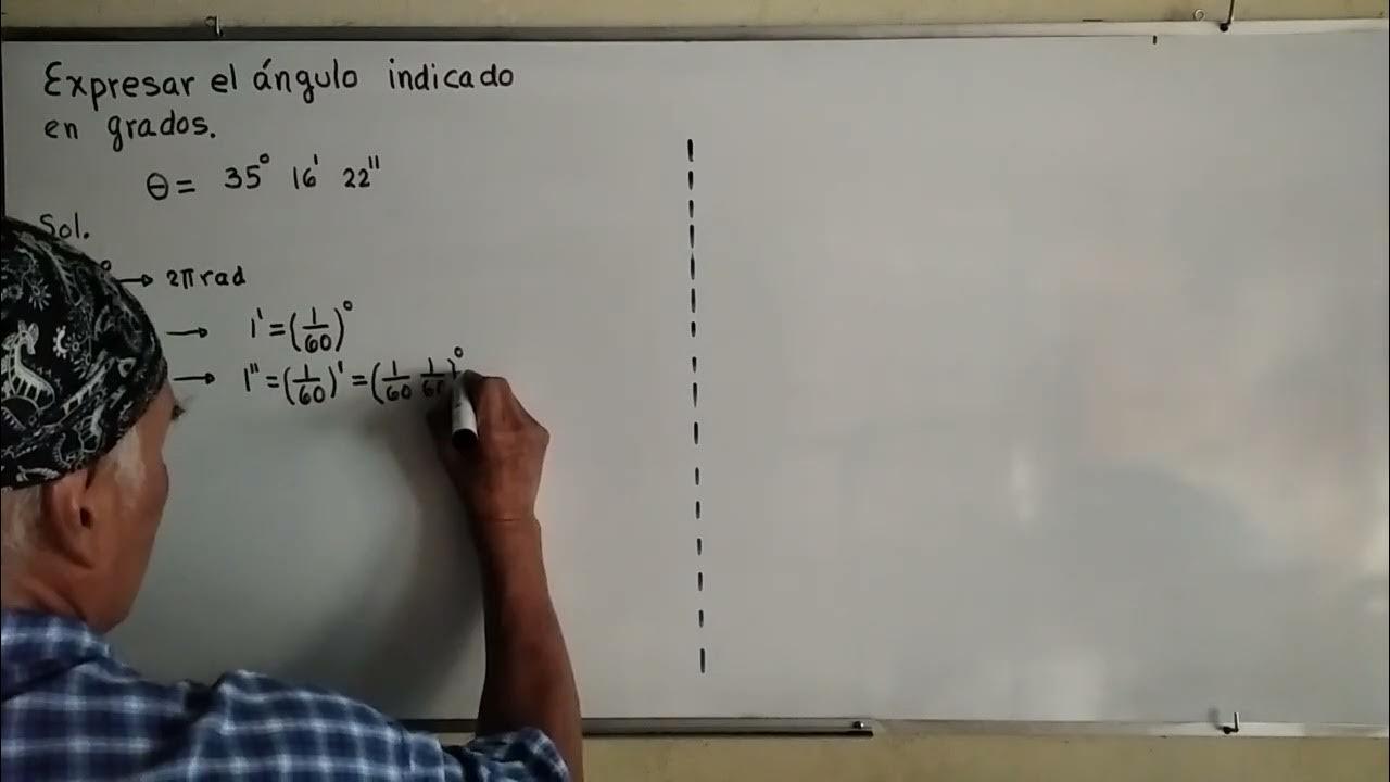
Ángulo en grados sexagesimales
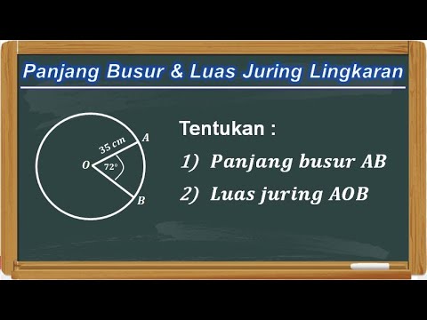
Cara Menghitung Panjang Busur dan Luas Juring Lingkaran

Making a Jig for Shaping Curves with Tom McLaughlin

experimento: CARTÕES FURADOS - ÓPTICA: PROPAGAÇÃO RETILÍNEA DA LUZ

Snell's law example 1 | Geometric optics | Physics | Khan Academy
5.0 / 5 (0 votes)