Introdução a Conceitos de Computação - Portas lógicas e expressões booleanas
Summary
TLDRIn this video lecture, the concepts of logic gates, Boolean expressions, and transistors in computing are introduced. The instructor explains how electrical signals in digital systems are used to represent binary values, enabling robust and error-resistant data handling. Key topics include the function of logic gates (AND, OR, NOT), their graphical representations, and how transistors control electrical flow within circuits. The lecture emphasizes how these fundamental components work together to perform complex tasks in modern computing, with a focus on circuit design and logic implementation using transistors. The video also sets the stage for exploring combinational circuits in future lessons.
Takeaways
- 😀 Digital signals in electronics are represented using binary values (0 and 1) based on voltage levels, with 0 being low (0-2V) and 1 being high (2-5V).
- 😀 Representing signals with binary values helps make systems more robust, especially when dealing with interference or noise.
- 😀 Transistors play a vital role in modern computing by switching between states quickly, enabling the creation of logic gates and circuits.
- 😀 A logic gate is a device that performs a basic operation on one or more input signals to produce a single output signal.
- 😀 Combining logic gates into circuits allows for complex logical operations and computation, including arithmetic and data storage.
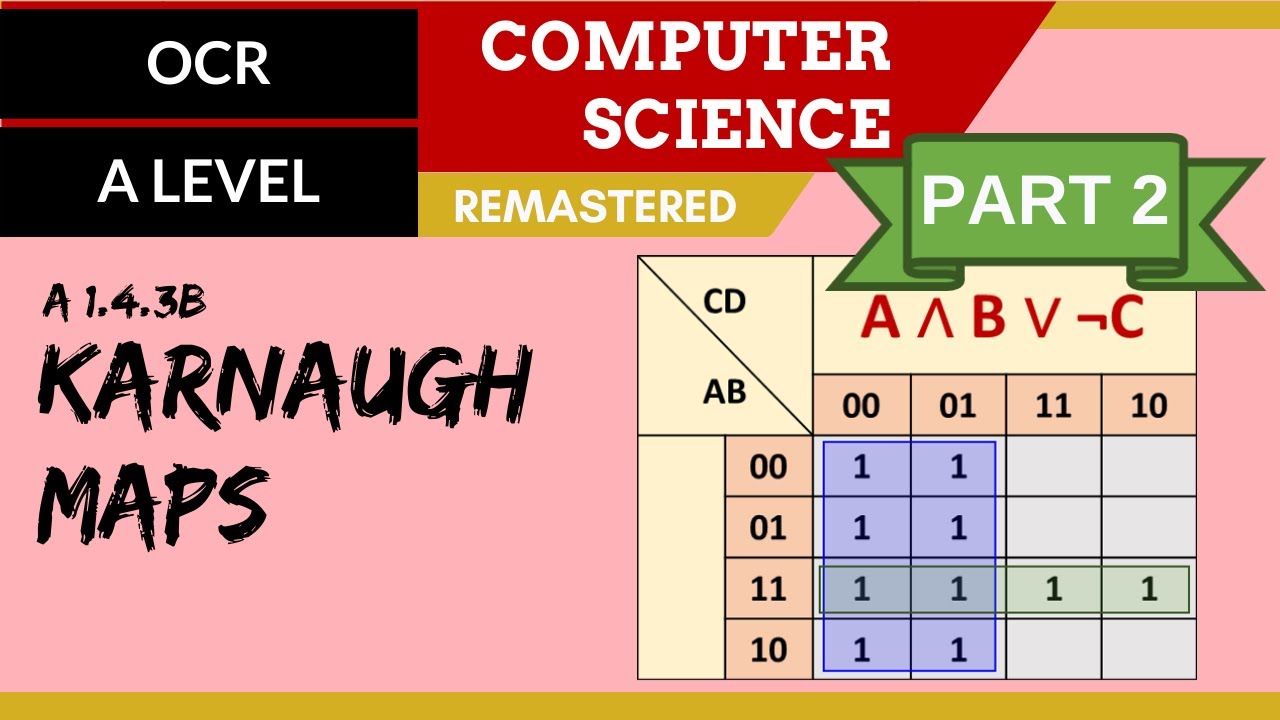
- 😀 The use of Boolean algebra allows for efficient and mathematical representation of logical operations, which is essential for designing circuits.
- 😀 A logic diagram visually represents the logical relationships between different gates, using symbols for each gate.
- 😀 Transistors serve as the building blocks for logic gates, acting as switches to control the flow of electrical current.
- 😀 The NOT gate inverts the input signal, producing an output that is the opposite of the input.
- 😀 The AND gate produces a high output only when all of its inputs are high, representing the logical AND operation.
- 😀 The OR gate outputs a high signal if at least one of its inputs is high, representing the logical OR operation.
- 😀 XOR (exclusive OR) gates output a high signal only when one input is high and the other is low, representing the logical XOR operation.
- 😀 The design of logical circuits using transistors and gates follows the principles of Boolean algebra, allowing for the construction of complex computational tasks.
- 😀 The next lesson will explore combinational circuits in more detail, building on the foundational knowledge of logic gates and transistors.
Q & A
What is the role of transistors in modern computing?
-Transistors are essential components in modern computing. They act as switches that control the flow of electricity, enabling the binary processing of data (represented by high or low voltage) and allowing for faster, more energy-efficient computers compared to older vacuum tube technology.
How does binary representation differ from analog signals in computing?
-In binary representation, signals are discretized into two states, typically represented by '0' and '1'. This contrasts with analog signals, which can vary continuously. The advantage of binary signals is their robustness against interference, making them more reliable for digital circuits.
What are logic gates and how do they function in computing circuits?
-Logic gates are devices that perform basic logical operations on one or more input signals to produce a single output signal. These gates are the building blocks of digital circuits, and when combined, they can perform complex operations such as arithmetic calculations or data storage.
What is the purpose of Boolean algebra in digital logic?
-Boolean algebra is used in digital logic to represent and simplify logical expressions. It allows for the systematic design and analysis of circuits by using binary variables (0s and 1s) and logical operators (AND, OR, NOT) to model complex logical relationships.
What is a NOT gate and how does it work?
-A NOT gate, also known as an inverter, takes a single input and inverts its value. If the input is high ('1'), the output will be low ('0'), and if the input is low ('0'), the output will be high ('1'). This operation is fundamental for controlling signal flow in circuits.
What is the difference between an AND gate and an OR gate?
-An AND gate outputs '1' only if both of its inputs are '1'. An OR gate, on the other hand, outputs '1' if at least one of its inputs is '1'. These gates are used to combine inputs in various ways to produce desired outcomes in digital circuits.
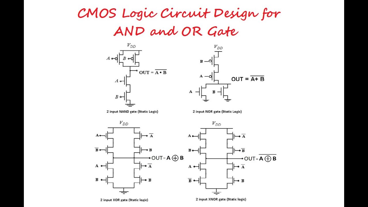
How does a NAND gate work and how does it differ from an AND gate?
-A NAND gate is the negation of an AND gate. It outputs '0' only if both inputs are '1'. Otherwise, the output is '1'. Essentially, it performs the opposite of an AND gate by inverting its output.
What is an XOR (exclusive OR) gate and how is it different from a regular OR gate?
-An XOR gate outputs '1' if exactly one of its inputs is '1', but it outputs '0' if both inputs are the same (either both '0' or both '1'). This gate is used when a condition requires exactly one input to be true, excluding the possibility of both being true at the same time.
What is the significance of transistor-based logic gates in circuit design?
-Transistor-based logic gates are fundamental in modern circuit design because they are compact, energy-efficient, and fast. These gates allow for complex operations in digital circuits, which are essential for everything from basic computation to high-performance processing in computers.
How does the ground (earth) connection influence the operation of transistors in a circuit?
-The ground (earth) connection in a transistor circuit helps maintain a stable reference voltage and ensures the safe flow of electricity. It prevents excessive voltage buildup, helping to protect sensitive components from damage and providing a reliable point for circuit grounding and signal referencing.
Outlines

This section is available to paid users only. Please upgrade to access this part.
Upgrade NowMindmap

This section is available to paid users only. Please upgrade to access this part.
Upgrade NowKeywords

This section is available to paid users only. Please upgrade to access this part.
Upgrade NowHighlights

This section is available to paid users only. Please upgrade to access this part.
Upgrade NowTranscripts

This section is available to paid users only. Please upgrade to access this part.
Upgrade NowBrowse More Related Video

102. OCR A Level (H046-H446) SLR15 - 1.4 Logic gates & truth tables
CMOS Logic Circuit Design for AND and OR Gate

Aljabar Boolean
99. OCR A Level (H046-H446) SLR15 - 1.4 Karnaugh maps part 2

Boolean Logic & Logic Gates: Crash Course Computer Science #3

How Do Computers Make Decisions? Logic Gates and Boolean Logic Explained.
5.0 / 5 (0 votes)