Diagrama de Operaciones del proceso
Summary
TLDRThe video tutorial explains the creation of an operations diagram essential for industrial engineers, detailing the chronological sequence of manufacturing processes for a lamp. It introduces key symbols like circles for operations and squares for inspections, emphasizing the importance of numbering each element independently. The speaker systematically outlines the components of the lamp, their respective operations, and how they combine into subassemblies. The tutorial underscores the necessity of understanding the production process to effectively represent and communicate operational flows, ultimately culminating in a clear, visually structured diagram.
Takeaways
- 😀 The operations diagram allows observation of the chronological sequence of all operations, inspections, and materials used in manufacturing or administrative processes.
- 🔧 Key symbols in the operations diagram include circles for operations and squares for inspections, each numbered independently.
- 💡 The process of manufacturing a lamp includes four main components: the support shaft, base of the socket, base, and lampshade, each undergoing specific operations.
- ✂️ The support shaft undergoes five operations: cutting, turning, drilling, painting, and inspection.
- 🛠️ The socket base involves two operations: cutting and inspection.
- 🔍 The base consists of six operations, including cutting, forming, drilling, sanding, painting, and inspection.
- 📦 The lampshade involves three operations: cutting, forming, and inspection.
- 🚫 Certain parts, such as the light bulb, socket, and electrical cord, are purchased ready-made and only require inspection before assembly.
- 📊 Sub-assemblies are created by combining components at various stages, with proper inspections at each stage to ensure quality.
- 📅 Proper documentation is essential, including headers in diagrams to identify the type of diagram, responsible department, and date of creation.
Q & A
What is the purpose of an operations diagram in manufacturing?
-The operations diagram allows engineers to observe the chronological sequence of operations, inspections, and materials involved in a manufacturing process.
What symbols are used in the operations diagram, and what do they represent?
-Two main symbols are used: circles represent operations, and squares represent inspections. Each symbol is numbered independently.
What are the four main components of the lamp mentioned in the script?
-The four main components are: 1) axis or support, 2) base of the socket, 3) base, and 4) lamp shade.
How many operations does the axis or support component undergo?
-The axis or support undergoes five operations: cutting, turning, drilling, painting, and a final inspection.
What is the process for assembling the lamp components?
-The assembly process involves creating subassemblies by combining components in a specified order, starting with the axis or support and including inspections at each stage.
Why are inspections important in the manufacturing process?
-Inspections ensure that each operation, such as cutting or drilling, is performed correctly and that the components meet the required specifications.
What is included in the header of the operations diagram?
-The header includes vital information such as the type of diagram, the method used, the responsible department, and the date of creation.
How are operations combined in the diagram?
-Operations can be combined into a single operation for components that are assembled together, represented by a new numbered circle in the diagram.
What additional pieces are mentioned that are not manufactured in-house?
-The additional pieces include the bulb, socket, and electrical cord, which are purchased pre-made and included in the assembly process.
How should the operations be represented graphically in the diagram?
-Operations should be represented using circles for operations and squares for inspections, following a logical sequence and properly labeled.
Outlines

This section is available to paid users only. Please upgrade to access this part.
Upgrade NowMindmap

This section is available to paid users only. Please upgrade to access this part.
Upgrade NowKeywords

This section is available to paid users only. Please upgrade to access this part.
Upgrade NowHighlights

This section is available to paid users only. Please upgrade to access this part.
Upgrade NowTranscripts

This section is available to paid users only. Please upgrade to access this part.
Upgrade NowBrowse More Related Video

Production Systems - Facilities & Manufacturing Support Systems

Industrial and Systems Engineers Make a Difference Everywhere

Role of Chemistry in Engineering
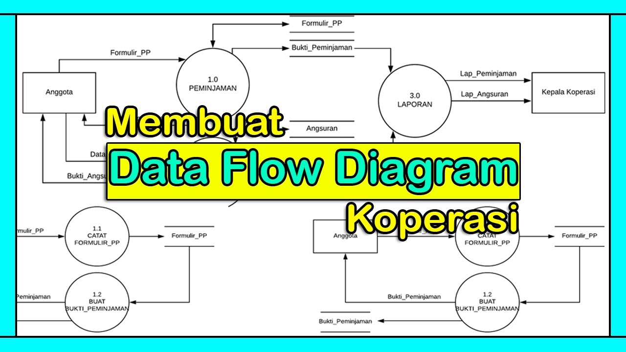
Tutorial Membuat DFD (Data Flow Diagram) | Studi Kasus Koperasi
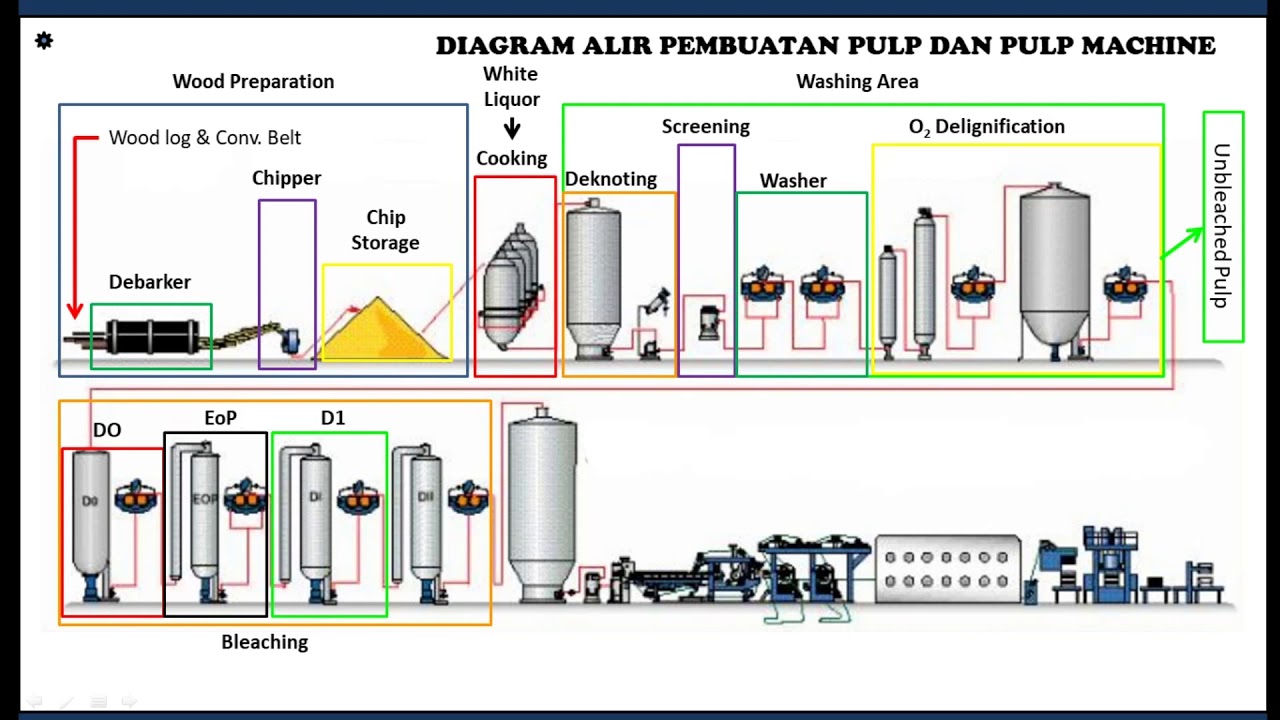
Kimia Industri - Pembuatan Pulp dan Kertas (Diagram Alir proses) (Bag. 2 - Akhir)
What is Industrial Engineering?
5.0 / 5 (0 votes)