5 Formulas Electricians Should Have Memorized!
Summary
TLDRThis video covers five essential formulas every electrician should know, starting with Ohm's Law, which explains the relationship between voltage, current, and resistance. It then explores Joule's Law, focusing on power transfer, and provides examples for calculating wattage and current. Voltage drop formulas for both single-phase and three-phase circuits are discussed, followed by methods for calculating resistance in series and parallel circuits. Lastly, the video covers horsepower calculations for motors, highlighting how efficiency and power factor impact motor output in both single-phase and three-phase systems.
Takeaways
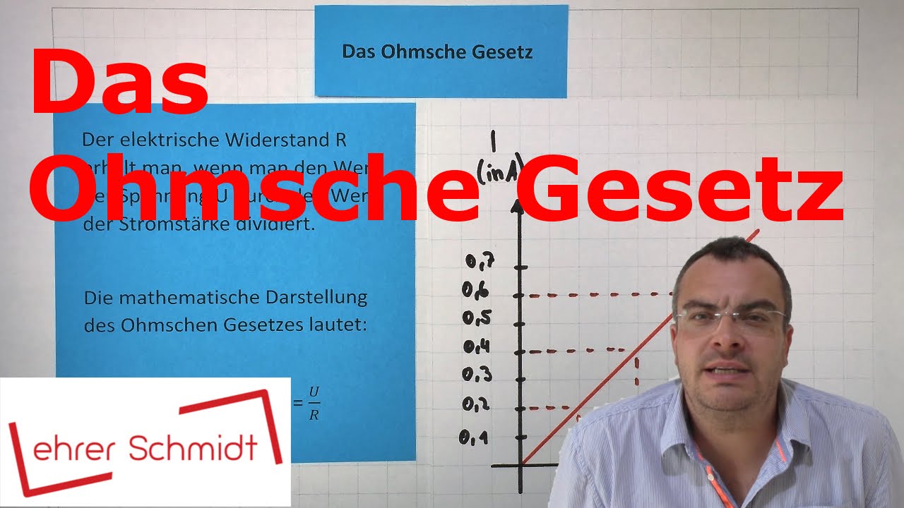
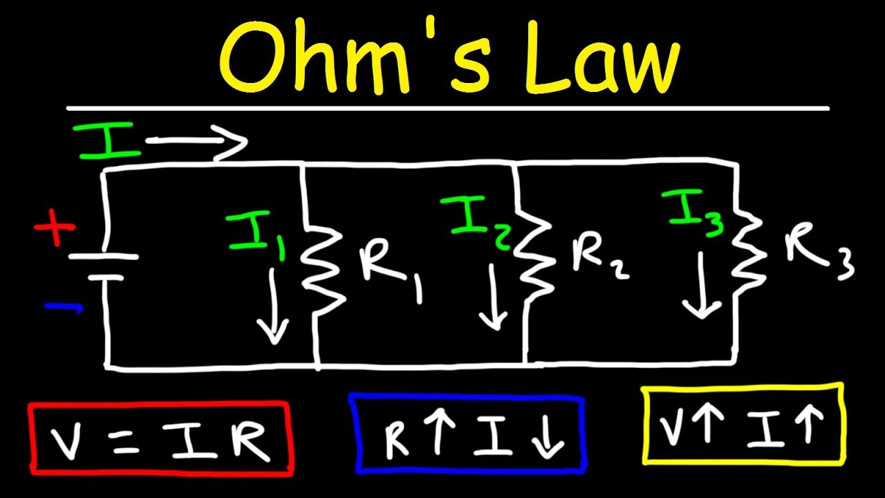
- ⚡ Ohm's Law explains the relationship between voltage, amperage, and resistance. It's often written as E = I * R.
- 🔌 To solve for a specific variable in Ohm's Law, cover the one you're solving for and use the appropriate equation, like E = I * R for voltage.
- 💡 Joule's Law relates to the amount of energy transferred between systems, commonly expressed as P = I * E.
- 🔋 Voltage drop can be calculated using formulas based on Ohm's Law, with additional factors like conductor length and material affecting accuracy.
- 🔗 In three-phase circuits, voltage drop calculations introduce the square root of 3 (1.732) for more accuracy.
- 🧮 For resistances in series, simply add them together. In parallel circuits, use the sum of reciprocals for total resistance.
- 📏 The product-over-sum method is an easier alternative to calculate parallel resistance compared to the sum of reciprocals method.
- ⚙️ One horsepower equals 746 Watts. However, motor efficiency and power factor influence the actual horsepower output.
- 🏎️ Three-phase motors generally produce more horsepower than single-phase motors due to more efficient power transfer.
- 📚 Advanced topics like capacitance, inductive reactance, and RLC circuits require additional study but are important for more complex electrical systems.
Q & A
What is Ohm's Law, and how does it relate voltage, amperage, and resistance?
-Ohm's Law describes the relationship between voltage (E), amperage (I), and resistance (R). It states that E = I × R. If you want to solve for one variable, you can rearrange the equation accordingly, such as I = E / R or R = E / I.
How can Ohm’s Law be used to calculate the amperage in a circuit?
-To calculate amperage using Ohm’s Law, divide the voltage by the resistance. For example, if you have 120 volts and a 6-ohm resistor, the amperage would be 120 / 6 = 20 amps.
What is Joule's Law, and how does it differ from Ohm’s Law?
-Joule's Law relates to the amount of energy transferred, particularly from electrical to another form, like light or heat. It is represented by P = I × E, where P is power (watts), I is current, and E is voltage. Unlike Ohm’s Law, which focuses on voltage, amperage, and resistance, Joule’s Law introduces power.
How can you calculate the total wattage of a circuit using Joule's Law?
-Using Joule's Law (P = I × E), if you know the voltage and the amperage, you can calculate total power. For instance, in a 120-volt circuit drawing 20 amps, the total power would be 120 × 20 = 2400 watts.
What is voltage drop, and how is it calculated in single-phase circuits?
-Voltage drop is the reduction in voltage in a circuit between the power source and the load. In single-phase circuits, it can be calculated using the formula VD = 2 × K × I × L / CM, where K is a material constant (12.9 for copper and 21.2 for aluminum), I is the current, L is the length of the conductors, and CM is the circular mils of the conductor.
Why is 1.732 used in three-phase voltage drop calculations?
-The value 1.732 is the square root of 3 and is used in three-phase voltage drop calculations to account for the three-phase system’s different power transfer characteristics compared to single-phase systems.
What is the difference in voltage drop between copper and aluminum conductors?
-Copper has a lower resistance than aluminum, leading to less voltage drop. The constant for copper (K = 12.9) is smaller than for aluminum (K = 21.2), meaning aluminum conductors experience more voltage drop for the same current and distance.
How do you calculate resistance in a series circuit?
-In a series circuit, the total resistance is the sum of all individual resistances. For example, if you have three resistors with values of 2 ohms, 3 ohms, and 4 ohms, the total resistance would be 2 + 3 + 4 = 9 ohms.
How do you calculate resistance in a parallel circuit?
-In a parallel circuit, resistance is calculated using the reciprocal method: 1 / RT = 1 / R1 + 1 / R2 + 1 / R3. For example, if you have resistors of 2 ohms, 3 ohms, and 4 ohms, you would calculate 1 / RT = 1 / 2 + 1 / 3 + 1 / 4. The total resistance would be the reciprocal of that sum.
What is the relationship between watts and horsepower?
-One horsepower is approximately equal to 746 watts. This means that to convert watts to horsepower, you divide the total watts by 746. For example, a motor producing 2400 watts would have a horsepower of 2400 / 746 ≈ 3.2 horsepower.
Outlines
⚡ Understanding Ohm's Law
The first paragraph introduces Ohm's Law, explaining the relationship between voltage, amperage, and resistance. It provides formulas for calculating each based on known values: E = I * R (voltage), I = E / R (amperage), and R = E / I (resistance). These formulas are essential for electricians to solve for missing electrical variables efficiently.
💡 Joule's Law and Power Calculation
This section dives into Joule's Law, which deals with the transfer of energy, such as when electrical energy converts to light or heat. The formula P = I * E (power) is introduced, which helps electricians calculate the total wattage in a circuit. The example given demonstrates using a 120-volt, 20-amp circuit to determine total power output. The explanation concludes with methods for calculating voltage, amperage, and wattage in practical settings.
🔋 Voltage Drop Calculations
This paragraph focuses on voltage drop and introduces the formulas to calculate it. It explains the use of constants for different conductor materials, such as copper (K = 12.9) and aluminum (K = 21.2). An example of a voltage drop calculation over a 100-foot distance is provided, illustrating how conductor type and amperage affect voltage drop in both single-phase and three-phase circuits.
🔀 Series and Parallel Circuits
This section explains the difference between series and parallel circuits, particularly focusing on how resistance is calculated in each. In series circuits, resistances are simply added together, while in parallel circuits, the inverse of the sum of inverses method is used. The paragraph also mentions an alternative method, the 'product over sum' approach, which simplifies the calculation of total resistance in parallel circuits.
🏇 Horsepower and Motor Efficiency
The final paragraph covers the calculation of motor horsepower, specifically comparing single-phase and three-phase motors. It explains the importance of factors like efficiency and power factor in determining motor output. The key formula used is horsepower = (voltage * amperage * efficiency * power factor) / 746. Examples are provided to show the difference between calculating for single-phase and three-phase motors.
Mindmap
Keywords
💡Ohm's Law
💡Voltage
💡Amperage
💡Resistance
💡Joule's Law
💡Power
💡Voltage Drop
💡Three-phase Circuit
💡Series Circuit
💡Parallel Circuit
Highlights
Ohm's Law defines the relationship between voltage, amperage, and resistance, without considering power.
To solve for any variable in Ohm's Law, cover the variable you're solving for: E = I * R for voltage, I = E / R for amperage, and R = E / I for resistance.
Joule's Law explains the transfer of energy between systems, such as electrical energy converting to light and heat in a light bulb.
Pi formula (P = I * E) is used to calculate power in electrical circuits, commonly used to find wattage in a circuit.
In field calculations, understanding voltage drop is important, and both Ohm's Law and specific voltage drop formulas can be applied.
In three-phase circuits, the square root of three (1.732) is introduced into the voltage drop formula, which generally results in a smaller voltage drop than in single-phase circuits.
The constant 'K' in voltage drop calculations varies depending on the conductor material: 12.9 for copper and 21.2 for aluminum.
For common calculations in the field, a #12 copper wire has a circular mils value of 6530, which is used in voltage drop formulas.
Series circuits' total resistance is the sum of all resistances, while parallel circuits require the reciprocal of the sum of the reciprocals for total resistance.
The product-over-sum method simplifies the calculation of resistance in parallel circuits, producing the same result as the sum of reciprocals.
One horsepower equals approximately 746 watts, and efficiency and power factor are key factors in calculating the true horsepower output of a motor.
In a three-phase motor, efficiency is improved over single-phase due to the 1.732 multiplier in the horsepower equation.
Capacitance and inductance formulas in series and parallel circuits differ, with capacitance formulas being inverted in parallel and series configurations.
Capacitance and inductance are more advanced electrical concepts often tested in electrical theory exams, requiring an understanding of RLC circuits.
Horsepower output is greater in three-phase motors due to more efficient power transfer, compared to single-phase motors under the same conditions.
Transcripts
here are five formulas every electrician should know [Music]
number one is Ohm's Law most electricians know this like they know nothing else with math it's
Ohm's law and Ohm's law is specifically the relationship between voltage amperage
and resistance only does not put into any uh Power efficiency anything like that once you
start getting into Power you're talking about the transferring of power from one thing to
another thing and that is a process of joules so uh the the next one we will talk about is
once we introduce power into this but Ohm's log and voltage amperage resistance now if you want
to solve for one of these you just cover the one you're trying to solve for and it tells you what
equation to to use so with Ohm's loss there's three different ways that you can structure it
so you could do the first one E equals I times R if you're trying to solve for voltage E equals
I times R just remember they're right next to each other I times R if you wanted to solve for
amperage you could sit and try to like divide out the r and move everything over or you just look
at this and be like I'm trying to solve for I so cover I it's e over R so super simple and lastly
as you would expect R equals e over I so that tool that little chart is really good because
then otherwise you'd have to like do all of this math and try to multiply by things and like move
things around but if we have an amperage that's 20 amps times a 6 Ohm resistor it's going to be
120 volts if you're trying to figure out how many amps is it I got 120 volt circuit and I know this
resistor is six ohms you just divide and you get 20 amps but if you don't know what the resistance
is of a resistor but you know that this thing is drawing 20 amps and it's 120 volt circuit
you can just divide that and figure out six ohms so this is a really really helpful thing to use
next is going to be Jules law so a lot of people don't call this Jewel's law but that's what it is
Jewels is the amount of energy that's produced by something or that's transferred from one system
to another system so when we're talking about electrical energy going through a light bulb we're
talking about the amount of energy that is coming from the electrical energy in the electrical
circuit and then is being produced or transferred into another kind of energy like light and heat
in the case of like an incandescent bulb so Jules law is usually a function of time so usually in a
formula they're going to have time as a function but amperage includes time so amperage is a rate
so it's current that's flowing per second so it already factors that in so we can call this
joules law and use it as such so very similar kind of thing instead of uh E equals I times R
now we have P equals I times E I just think of Pi Yami pi all right p-i-e Pi that's how I think of
it so the one thing if we're trying to solve for how many uh watts of like light bulbs that we have
um What's the total wattage of a circuit once we turn all these bulbs on well we know it's 120 volt
circuit and uh we know that it's drawing 20 amps so how much total power is that it's going to be
2400 so we could take all of these values and the same thing all of them are true if we're
trying to figure out how much current draws in a circuit well we know we have 2400 watts in a
circuit and say we're trying to figure out like a 20 amp breaker you know 20 amp circuit well
if it's 2 uh 2400 Watts that we have to deal with divided by 120 then that's going to be
20 total amps for that circuit you could also do the inverse so say that we're trying to figure out
um figure things out for what the total wattage of a circuit is if we have a 20 amp breaker 120
amps then we have 2400 watts to play with in a 20 amp circuit that's another like helpful thing out
in the field so so anyways lastly if we're trying to solve for voltage which you're never going to
do you're going to take the power whatever the the wattage is divide that by 20 amps if you're
testing 20 amps and it should be 120 volts so they all organize nice and neatly again rather
than doing the math to try to figure out and like divide by E to isolate I and move e over here
you'll have to remember all that just remember the pie chart next up is voltage drop so voltage drop
is something we're very frequently going to come across in the field you can actually use Ohm's
law to do a voltage drop calculation without all the extra variables it's just slightly off it's
not going to be as accurate but kind of like gets you relatively close but a better way to
do voltage drop is to actually use voltage drop formulas you know I have two here one of them is
VD voltage drop the other one is vd3 for three phase so anytime you do three phase you have to
introduce 1.732 into the formula it's also the square root of three so the square root of 3
equals 1.732 so you're going to notice the formulas then are very similar one of them
is two times a bunch of craziness the other one's 1.732 times a bunch of craziness which that means
this is a smaller number you're multiplying by so that typically in a three-phase circuit
there's going to be slightly less voltage drop voltage drop is more expressed in a single phase
circuit all right so voltage drop Let's do an example so the two I I think of it there's two
conductors right you have there and back we have length which is L so if you have a hundred feet
you're not going to measure 100 feet one way and 100 feet back the other way that's what that 2
is for so the two two conductors at 100 feet that's how I remember the two and the L the K
is a constant that we use depending on the type of material that we're using so if we're using a
copper conductor the conductivity or resistivity of a certain conductor is going to be different
so aluminum is a little bit less conductive than copper is so copper you're not going to experience
as much of a voltage drop as you are for the same size conductor in aluminum just because they don't
conduct as well there's just more resistance with the material so K the coefficient for k for copper
is 12.9 so every single one of these that you ever do you're going to use 12.9 for copper if
it's going to be aluminum K is going to be 21.2 so just memorize those two numbers and never forget
them the rest of your life and you'll be fine so anytime you're doing aluminum stuff use that
anytime I'm using copper use that so that covers the two the k i is your amperage how like if we
had a motor or something that's a 20 amp motor out in the field you're gonna plug in whatever that
is going to be so that takes care of everything on the top the bottom is not centimeters it is
circular Mills so every conductor has a certain diameter which means it also has an area and the
area of that conductor or the cross-sectional area if you slice the thing in half the cross-sectional
area of it is measured in Mills or circular Mills so a circular conductor is going to be
circular Mill so every conductor has a certain size circular mils number 12 I know for 20 amps
is going to be 6530 just remember that remember that number because most of the time you're going
to be dealing with number 12 conductors and trying to see what the voltage drop is on that
sized conductor so the cross-sectional area of number 12 is going to be 6530.
um now one thing to keep in mind if you're ever dealing with like 250 KC mil or 250 MCM or like
500 600 you're talking big conductors the 600 actually means 600 000 circular Mills so those
are really easy once you get past 4i you start 250 300 350 all of that that's actually talking
about the circular Mills so uh otherwise chapter nine table eight NEC um it's going to have all
of these values in there for each specific one so beyond all of that like that's what we're
plugging into the formula so an example is say we've got a single phase voltage drop that we're
trying to calculate we've got a hundred foot distance there's two conductors they're copper
so it's 12.9 it's a 20 amp load divided by number 12 conductors which is 6530 we get eight volts so
in this situation over a hundred feet if we have a 20 amp motor on copper conductors it's number 12
we're going to experience an 8 volt drop when we hit that thing and actually start it up it's going
to drop the whole voltage of the circuit now for three phase again we see this 1.732 thing square
root of three right because it's three phase so everything three phase we've got to add this 1.732
thing so we have square root of 3 times 21.2 this time instead of copper we're going to say we're
using aluminum just to see what that does still a 20 amp load still 100 feet away and we're still
using number 12 it's just number 12 aluminum this time do all of the math and we figure
it's an 11 volt drop so other than we changed and put 1.732 instead of two this voltage drop if it
were both single phase just changing the aluminum conductors would have still made this thing drop
a lot more volts it's actually less of a voltage drop because we're in a three-phase circuit so it
would probably be higher maybe 12 volts if we were just doing single phase but even when you go up in
aluminum for that higher coefficient you go down because it's three phase just slightly next up
you're going to see this on every damn test you're ever going to take electrical Theory this stuff
sucks especially once you start getting into RLC circuits where you've got resistance inductance
and capacitance in series and in parallel and sometimes when you're doing capacitance these
formulas for capacitance are actually completely inversed so capacitance in a parallel circuit is
going to look like this capacitance in a series circuit is going to look like this but not to
digress series and parallel resistance if you're trying to figure out the total resistance of a
series circuit you just add all the resistances together it's the sum of all of them it's super
easy to do you're in series you're just adding one after the other so the total resistance or RT is
equal to the first resistance second resistance third resistance and as many resistances as you
got you just keep adding all together where it gets kind of wonky is when we get to parallel
resistance parallel resistance you have to take the inverse of the sum of inverses there's a
different method product over sum we'll get to that here in the next slide but it's a weird thing
right so I just usually do like one divide if it's a 3 Ohm resistor or something I do one divided by
three plus one divided by two plus one to whatever and you get that sum and then you take one divided
by whatever that sum is and that's what you get so you'll see the dramatic inverse effect on putting
resistors in a series circuit than you will in a parallel circuit all right series and parallel so
here we have a series circuit we've got R1 R2 and R3 there are three different resistors our one is
two ohms R2 is 3 ohms R3 is 4 Ohms so we're doing Series right they're all in series so we're going
to do the sum of all resistances method we're going to take the total resistance equals R1
R2 and R3 all added together so we got two plus three plus four two three four that's nine ohms
of resistance there's a lot of resistance because we have each one of them in series
so it's adding more and more resistance to the Circuit when we try to apply pressure or voltage
the next method is the reciprocal over the sum of reciprocals so we were going to take still R1 and
R2 and R3 but in this circuit we're in parallel rather than in series so we've got resistor one
two ohms still three ohms still and four ohms still we're just putting them in parallel in
the circuit instead and what we get is one over one half right because the two plus one third
because of the three plus one fourth because of the four we add all that up and then we take
the reciprocal of it and it's 0.9 ohms rather than nine ohms so we actually get the inverse
number um because it's going through current is traveling through the circuit differently it's not
just one resistance being added to each current's going to go everywhere in this circuit but there's
nothing impeding it um in a row in order so you can sit and mess around with that and have fun
if you want to but I find an easier method of going about it is just to use the product over
some method so you can do this craziness if you want to but it's also possible to just do each
one of the resistances times each other and then put over each one of the resistances added to each
other so the product 2 times 3 times 4 the product over the sum to plus 3 plus 4 and you get the same
exact number so super helpful you're going to run into lots of that once you start getting into
taking your electrical Theory exams so have fun last one we're going to talk about is horsepower
and we're specifically talking about the output of a motor what is it going to put out based off the
conditions of the circuit and the conditions of the motor talking about just converting a watt to
a horsepower because one horsepower equals roughly 746 Watts that's another number just remember that
if you're ever trying to think of like hey one horsepower motor what does that produce 746 Watts
roughly but there's a lot more things to factor with a motor some Motors are a lot more efficient
than other Motors a lot of them have a rating on them and it'll say eff and it'll give you
efficiency of like 90 or 0.9 so it's not a hundred percent efficient it's only 90 efficient so that's
going to change the Dynamics of the output of that motor another thing is you could have a
power factor problem so you might be in a building that's got a lot of inductive loads like maybe
tons of motor loads well the overall power factor of that circuit is going to change the nature of
the output of that motor so um we're going to be putting in voltage amperage the efficiency of the
motor the actual power factor for the circuit and we're going to divide by 746 right because
one horsepower equals 746 Watts so to figure out what the true horsepower of this motor is let's
look at an example so we're going to be single phase three phase again we got the square root
of three thing right three phase so let's look at a single horsepower motor we're going to take the
voltage times say it's a 240 volt circuit we've got a 20 amp motor the efficiency on the motor
actually says it's only an 80 percent efficient motor so not very great and the power factor is
kind of crazy at 0.7 so Unity power factor would be one if it's a hundred percent power factor that
means your voltage and your your amperage when you apply voltage is immediate amperage there's
no like delay or lag reactance that's happening um then you're gonna have one but anything that's
worse than that is going to be like below one so 0.7 is a pretty terrible power factor
then we're going to divide by 746 so we do all the math single phase horsepower we get 3.6
horsepower now that's not the actual horsepower rating sizing your conductors and doing amperage
and all of that stuff off of that you're going to use 430 in the National electrical code uh
247 248 249 and 250 and that's going to be you know single phase three-phase DC so now when we
look at a three-phase situation we have to add the 1.732 so that's that's going to help our
number a little bit because we're actually adding more it's not like two times everything but it is
1.732 times everything so square root of 3 is 1.732 times 240 volts same circuit uh 20 amps
0.9 on the efficiency this time so this is a much more efficient motor
but power factor is still 0.85 which is still better than it was and then we're dividing by
7.46 and we get 8.5 horsepower out of that circuit now this is a three-phase circuit
right we've got three conductors going into it it's on a three-phase breaker and we're hooking
it up so there's going to be just naturally more power transfer between three-phase circuit and a
three-phase motor whereas a single phase we've got two conductors that are probably pulsing a
lot differently but typically horsepower output for a three-phase motor is going to be slightly
greater than it is for a single phase motor if we were to keep all the numbers the same
the equations would be the same but you would have 1.732 times the output of that motor
so it's actually going to be more output on a three-phase motor than it is on a single phase
motor so those are all of your formulas that's actually not all of them if you really wanted to
get into capacitance or you wanted to get into like inductive reactants capacitive reactants
you want to get into RLC circuits there's more stuff to learn there's quite actually there's
quite a few more like formulas that you might want to know if you want to get into like trig
or calculus weird stuff like that but we don't because this is YouTube and we're all dummies
kidding I love you YouTube all right I'll see you crazy people in the next one thanks for watching
Browse More Related Video
FISIKA Kelas 12 - Rangkaian Arus Searah | GIA Academy
Resistors | Electricity | Physics | FuseSchool
Series and Parallel Circuits | Electricity | Physics | FuseSchool
Chapter 2 - Fundamentals of Electric Circuits
Lecture5: Single Loop Circuits
Basic Electrical Engineering | Module 2 | Analysis of Single Phase AC | Part 1 (Lecture 12)
5.0 / 5 (0 votes)