Autorretención de un Contactor | Circuito de Marcha y Parada | Enclavamiento
Summary
TLDRThis video tutorial offers a quick guide on how to wire a contactor with start and stop functionality. It covers the essential components, including a thermal magnetic switch rated at 20 amperes, green start button (normally open), red stop button (normally closed), and the contactor itself. The contactor operates by energizing its coil to close power and auxiliary contacts. The video demonstrates the wiring process, starting with the connection of phase output to the stop button, then to the start button, and finally to the contactor's auxiliary contacts. It also explains the feedback loop that locks the contactor's coil energized. The tutorial concludes with a practical demonstration using a light bulb as a load, showing how the start and stop buttons control the contactor and the connected load.
Takeaways
- 🔌 The video explains how to wire a magnetic thermal switch (PTM) and a contactor for a start/stop circuit.
- 🔘 A 20-ampere PTM is used for protection against overloads and short circuits.
- 🟢 A normally open green button is used for the start function.
- 🔴 A normally closed red button is used for the stop function.
- 🔩 The contactor is crucial; it closes its power and auxiliary contacts when its coil is energized.
- 🔋 The contactor's coil requires a 220-volt AC supply at 50 or 60 Hz.
- 🔄 The contactor has main power contacts (L1, L2, L3) and auxiliary contacts (13, 14) for control purposes.
- 🔄 Upon energization, the contactor's movable part retracts, connecting the main power lines and establishing a feedback loop.
- 🔄 The wiring involves connecting the phase output to the stop button, start button, auxiliary contact, and coil.
- 🔄 The control circuit can have a separate power supply from the main power contacts.
- 💡 The video demonstrates the circuit operation using a light bulb as a load instead of an electric motor.
Q & A
What is the main topic of the video?
-The video explains how to wire a contactor with start and stop functionality.
What is the purpose of the thermal magnetic switch (PTM) mentioned in the video?
-The thermal magnetic switch (PTM) serves as an overcurrent and short-circuit protection for the electrical circuit.
What are the two types of push buttons used in the circuit?
-The two types of push buttons used are a green start button, which is normally open, and a red stop button, which is normally closed.
What is the voltage and frequency requirement for energizing the contactor's coil?
-The contactor's coil must be energized with 220 volts at 50 or 60 hertz AC.
What are the main components of the contactor mentioned in the video?
-The main components of the contactor are the coil, main power contacts (L1, L2, L3 to T1, T2, T3), and auxiliary contacts (13 and 14).
How does the contactor's auxiliary contact (13-14) play a role in the circuit?
-When the contactor's coil is energized, the auxiliary contact closes, creating a feedback loop that latches or maintains the energization of the coil.
What is the function of the thermal relay in the context of this video?
-Although not the main focus of the video, the thermal relay is mentioned as an additional protective element for a motor, which will be explained in more detail in another video.
What is the wiring process described for the start and stop push buttons?
-The stop button (normally closed) is connected to the phase output terminal, then to the start button (normally open), and from there to the contactor's A1 terminal. The wiring from the push buttons is also connected to the contactor's auxiliary terminal 13.
How is the control circuit powered in the video?
-The control circuit can be powered independently from the power supply of the main contacts.
What happens when the stop button is pressed?
-Pressing the stop button de-energizes the circuit, breaking the feedback loop and causing the contactor's coil to de-energize, which opens the main and auxiliary contacts.
What is used as a load in the practical demonstration of the contactor circuit?
-A light bulb is used as a load in the practical demonstration to test the contactor circuit.
Outlines

This section is available to paid users only. Please upgrade to access this part.
Upgrade NowMindmap

This section is available to paid users only. Please upgrade to access this part.
Upgrade NowKeywords

This section is available to paid users only. Please upgrade to access this part.
Upgrade NowHighlights

This section is available to paid users only. Please upgrade to access this part.
Upgrade NowTranscripts

This section is available to paid users only. Please upgrade to access this part.
Upgrade NowBrowse More Related Video
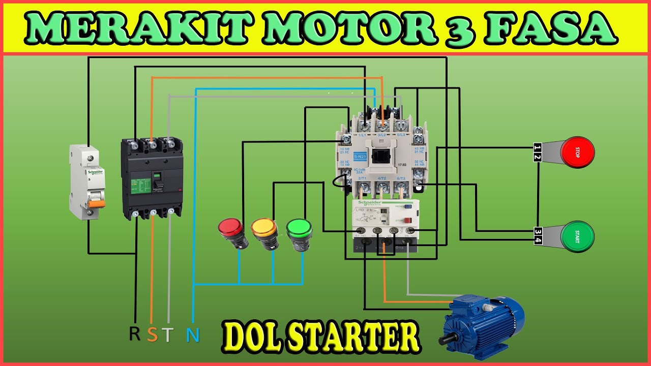
How to assemble a 3-phase motor DOL starter (direct on line) circuit

Cara Kontrol On/Off Motor Listrik dengan Kontaktor

Single Phase Direct Online Starter DOL Wiring - Connections Explained and Setting the Overload

Build an electric transformer (DIY)
Cara Kerja VSD Variable Speed Drive || VFD

Motor Starter
5.0 / 5 (0 votes)