KONGSBERG Simulator l Engine - How to start Diesel Generator #1 and supply power
Summary
TLDRThis instructional video script details the process of preparing and starting a diesel generator, covering five essential systems: freshwater, fuel, starting air, lube oil, and seawater. It guides through checks, valve operations, and connections to the bus bar, concluding with supplying power to consumers and setting the generator to automatic priority one, offering a comprehensive overview for those learning to operate such equipment.
Takeaways
- 🛠️ The diesel generator requires five systems to be prepared before operation: freshwater, fuel, starting air, lube oil, and seawater systems.
- 💧 The freshwater system includes components like the lt cooler, hd cooler, healthy pump, and hd pump, and it's crucial to check and maintain the expansion tank level at 50%.
- 🔥 The fuel system involves two filters, a fuel pump, and a three-way valve for diesel and HF changeover, with service tanks for HFO and DO.
- 🌬️ The starting air system includes main and emergency compressors, air receivers, and requires checking the pressure and ensuring the system is properly charged.
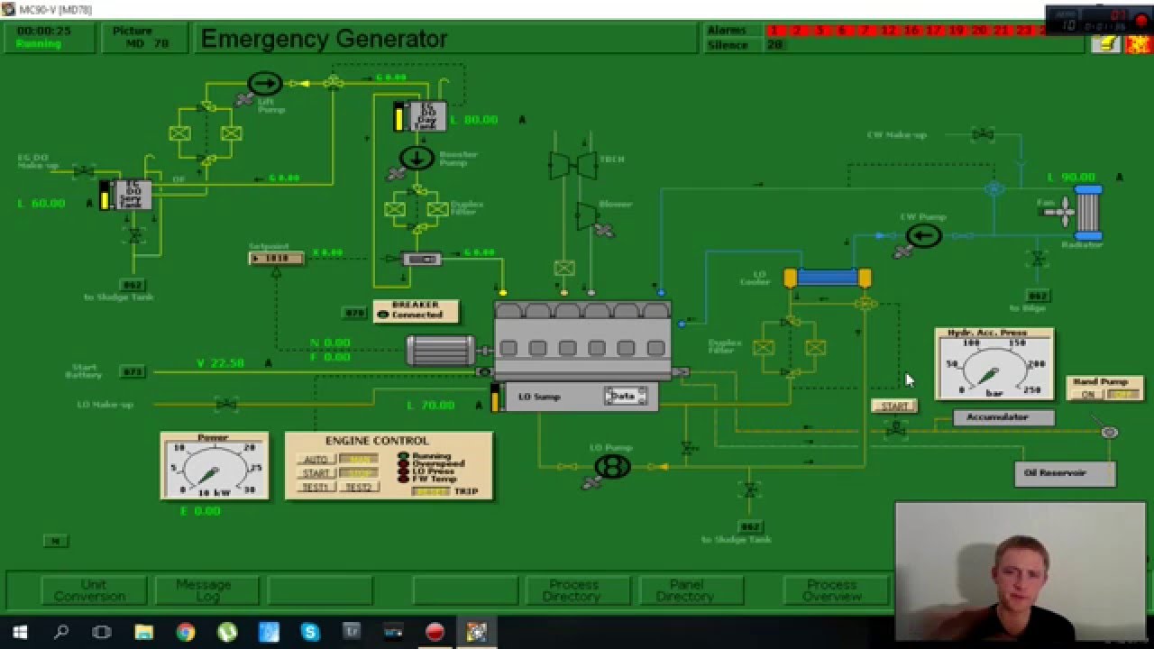
- 🛢️ The lube oil system has low boil pumps, a priming pump, lube oil cooler, and filters, with procedures to rectify low level alarms and prepare the system for engine operation.
- 🌊 The seawater system, color-coded green, includes components for cooling and flow indicators, and requires checking the seawater pumps and coolers.
- 🔄 Preparation of each system involves checking levels, opening valves, switching on components, and ensuring all parts are functioning correctly.
- 🚀 After preparing the systems, the diesel generator can be started by setting it to local control and monitoring the RPM before switching to remote control.
- 🔌 Connecting the diesel generator to the main bus bar involves ensuring the output voltage is correct and transferring the load from the emergency generator.
- 🔑 The process of supplying power to consumers includes starting auxiliary systems like air ventilation and setting the diesel generator to priority one automatic.
- 🔧 Troubleshooting involves checking for alarms, ensuring all components are in auto mode, and rectifying any issues before the generator can be set to automatic.
Q & A
What are the five systems needed by a diesel generator to run?
-The five systems needed by a diesel generator to run are the freshwater system, fuel system, starting air system, lube oil system, and seawater system.
What is the purpose of the freshwater system in a diesel generator?
-The freshwater system is used for cooling the diesel generator's components, specifically the jacket cooling of the engine.
How do you prepare the freshwater system for a diesel generator?
-To prepare the freshwater system, you need to check the expansion tank level and maintain a 50% level. If necessary, fill up the tank from the hydrophore tank, and then switch on the pre-heater to raise the jacket cooling inlet temperature.
What are the components of the fuel system in the diesel generator as described in the script?
-The fuel system components include filter number one, filter number two, the fuel pump, a shock of bulb, a three-way valve, and connections to the diesel oil and HF (Hydraulic Fluid).
How do you prepare the fuel oil system for the diesel generator?
-To prepare the fuel oil system, open the filter valves, the shut off bulb, and check that the three-way valve is selected to diesel. Ensure the valves in the service tank are open and that the fuel oil service tanks are connected properly.
What is the function of the starting air system in a diesel generator?
-The starting air system provides the necessary air pressure to start the diesel generator. It includes main compressors, emergency starting air compressor, and air receivers.
How do you check the starting air system pressure and prepare it?
-Check the pressure gauge on the starting air system. If the pressure is low, go to diagram number 59 to investigate and open the necessary valves. Start the compressor and wait for the alarm to disappear to prepare the system.
What is the role of the lube oil system in a diesel generator?
-The lube oil system is responsible for lubricating the engine components to reduce friction and wear. It includes lube oil pumps, coolers, filters, and a priming pump.
How do you rectify a low level alarm in the lube oil system?
-To rectify a low level alarm, open the valve coming from the storage tank and wait for the level to reach 50%. Then close the valve and proceed to prime the engine.
What is the seawater system's role in a diesel generator?
-The seawater system is used for cooling various components of the diesel generator, including the freshwater coolers and other heat exchangers.
How do you ensure proper seawater flow in the diesel generator system?
-Check the flow indicators and go to diagram number 01 if there is no seawater flow. Ensure the seawater pumps are operational, and the necessary valves such as the recirculation valve and the 3-way bulb valve are set to auto.
What steps are involved in starting the diesel generator and connecting it to the main bus bar?
-After preparing all five systems, go to the engine control and start the diesel generator. Monitor the RPM, and once it reaches 900, set the preheater, priming pump, and engine control to auto. Then, in model diagram 70, connect the generator to the main bus bar, transfer the load from the emergency generator, and supply power to the consumers.
How do you transfer the load from the emergency generator to diesel generator number one?
-In model diagram 70, select diesel generator 1, click the connect button to connect it to the main bus bar. Then, transfer the breaker from the emergency generator to diesel generator 1, ensuring to restart the auxiliary seawater pump if necessary to prevent a trip due to loss of cooling.
What is the final step to ensure the diesel generator is operating automatically and supplying power?
-After supplying power to the consumers, go to panel directory 101, check that the ready indicator light for diesel generator 1 is green, then click priority one and automatic to set the generator to operate in automatic mode.
Outlines

This section is available to paid users only. Please upgrade to access this part.
Upgrade NowMindmap

This section is available to paid users only. Please upgrade to access this part.
Upgrade NowKeywords

This section is available to paid users only. Please upgrade to access this part.
Upgrade NowHighlights

This section is available to paid users only. Please upgrade to access this part.
Upgrade NowTranscripts

This section is available to paid users only. Please upgrade to access this part.
Upgrade NowBrowse More Related Video

Auxiliary Generator Starting Procedure from Blackout condition | Garish Jerome
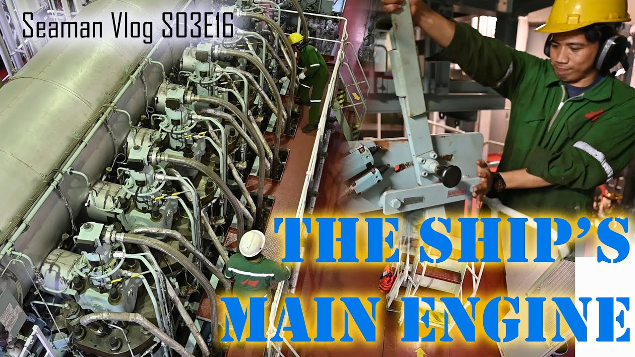
How To Start The Ship's Main Engine : From Preparation to Full Away
How to start a ship from Cold Condition " lesson 1 "
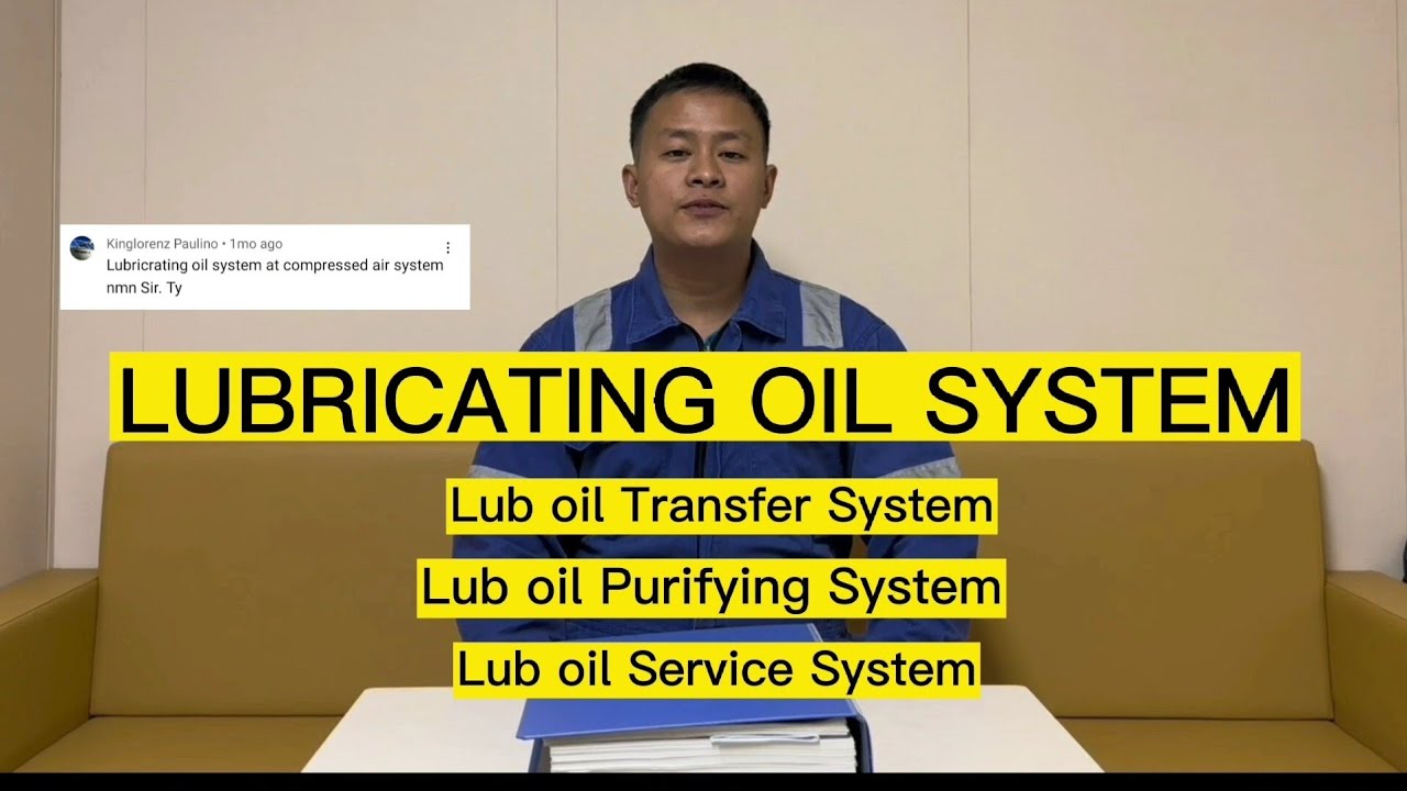
LUBRICATING OIL SYSTEM |Toping's World

Simulasi Sampling Emisi Sumber Tidak Bergerak

How a Ship Engine Works - 2-Stroke Marine Diesel Engine
5.0 / 5 (0 votes)