Butterworth Filter : Design of Low Pass and High Pass Filters
Summary
TLDRThis video delves into the design of Butterworth filters, focusing on both low pass and high pass configurations using the Sallen-Key topology. The presenter explains the theory behind the Butterworth approximation, highlighting the flat passband and its roll-off rate. It covers the step-by-step process of designing second, third, and higher-order Butterworth filters and the key factors like the quality factor (Q) for achieving a smooth response. Additionally, the video touches on practical exercises for filter design, offering a detailed explanation of the required components and formulas for creating both low pass and high pass filters.
Takeaways
- 😀 The Butterworth filter has a flat passband and a roll-off of 20n dB per decade. For example, a 4th-order filter has a roll-off of 80 dB per decade.
- 😀 The transfer function of a second-order low pass filter can be written in terms of gain (k), cutoff frequency (omega_n), and quality factor (Q).
- 😀 Cascading two first-order low-pass filters cannot design a Butterworth filter because it requires a higher quality factor (Q).
- 😀 The Sallen-Key filter topology is commonly used for Butterworth filter design, providing positive feedback and active components.
- 😀 The quality factor (Q) represents the amount of peaking around the cutoff frequency. For Butterworth design, Q is 0.707.
- 😀 By adjusting the gain (k) in the Sallen-Key filter, you can control the quality factor (Q) and design a Butterworth filter with the desired properties.
- 😀 The design of the Butterworth low-pass filter requires a specific gain (k), with k = 1.586 for the standard Butterworth filter with Q = 0.707.
- 😀 The Butterworth filter can be cascaded with multiple second-order filters to create higher-order filters for better roll-off performance.
- 😀 The polynomials used for second-order low-pass Butterworth filters can be applied to design higher-order filters with a desired cutoff frequency.
- 😀 The process for designing Butterworth high-pass filters is similar to low-pass filters, except the positions of resistors and capacitors are interchanged.
Q & A
What is a Butterworth filter and what is its key characteristic?
-A Butterworth filter is a type of signal processing filter known for having a maximally flat passband. Its key characteristic is that the roll-off rate is 20n dB per decade, where 'n' is the filter order.
How does the roll-off rate change for different order filters in Butterworth design?
-The roll-off rate in a Butterworth filter increases with the filter order. For example, a 4th order filter has a roll-off of 80 dB per decade, and an 8th order filter has a roll-off of 160 dB per decade.
What is the formula for the transfer function of a second-order low-pass filter?
-The transfer function of a second-order low-pass filter is given by k * ωc² / (s² + (2/RC)s + ωc²), where k is the gain, ωc is the cutoff frequency, and RC is the product of resistance and capacitance.
Why does cascading first-order filters not work for designing a Butterworth filter?
-Cascading first-order filters does not work for designing a Butterworth filter because it doesn't provide the necessary value of the quality factor (Q). The Butterworth design requires a Q of 0.707, which is achieved through active components and positive feedback.
What is the role of the quality factor (Q) in a Butterworth filter design?
-The quality factor (Q) in a Butterworth filter determines the amount of peaking around the cutoff frequency. A Q value of 0.707 ensures the filter has a maximally flat passband with no peaking at the cutoff frequency.
How is the quality factor (Q) calculated in a Sallen-Key low-pass filter?
-In a Sallen-Key low-pass filter, the quality factor (Q) can be calculated using the formula Q = 1 / (3 - k), where k is the gain. The value of k should be less than 3 to maintain system stability.
How do you determine the value of 'k' for a Butterworth filter design using a Sallen-Key topology?
-The value of 'k' for a Butterworth filter design is determined by the equation 1.414 = 3 - k. Solving this gives k = 1.586, which is used to calculate component values in the design.
What is the importance of the feedback network in a Sallen-Key filter for Butterworth design?
-The feedback network in a Sallen-Key filter allows for positive feedback, which is necessary to achieve the required Q value for Butterworth filter design. Without it, you cannot achieve the flat passband required for a Butterworth filter.
How do you design a third-order Butterworth low-pass filter?
-To design a third-order Butterworth low-pass filter, you cascade a second-order Sallen-Key Butterworth filter with a first-order RC low-pass filter. This ensures the desired transfer function and cutoff frequency.
How does the design process differ when creating Butterworth high-pass filters compared to low-pass filters?
-The design process for Butterworth high-pass filters is similar to low-pass filters, except that you interchange the positions of the resistor and capacitor in the Sallen-Key topology to create a high-pass configuration.
Outlines

このセクションは有料ユーザー限定です。 アクセスするには、アップグレードをお願いします。
今すぐアップグレードMindmap

このセクションは有料ユーザー限定です。 アクセスするには、アップグレードをお願いします。
今すぐアップグレードKeywords

このセクションは有料ユーザー限定です。 アクセスするには、アップグレードをお願いします。
今すぐアップグレードHighlights

このセクションは有料ユーザー限定です。 アクセスするには、アップグレードをお願いします。
今すぐアップグレードTranscripts

このセクションは有料ユーザー限定です。 アクセスするには、アップグレードをお願いします。
今すぐアップグレード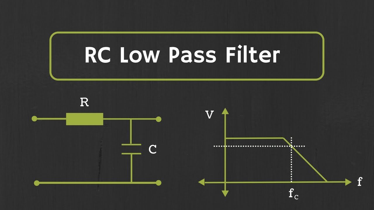


5.0 / 5 (0 votes)
