How does Starlink Satellite Internet Work?📡☄🖥
Summary
TLDRThis script delves into the revolutionary technology of Starlink, a satellite internet system. It explains how a pizza-sized dish transmits data to satellites orbiting 550 km above Earth, using phased array antennas and beamforming to maintain a focused beam for high-speed data transfer. The video explores the inner workings of the satellite dish, the communication process between the dish and the satellite using 64QAM, and the challenges of sending and receiving signals in a rapidly moving environment. It offers a detailed look at the engineering marvels that make satellite internet both feasible and efficient.
Takeaways
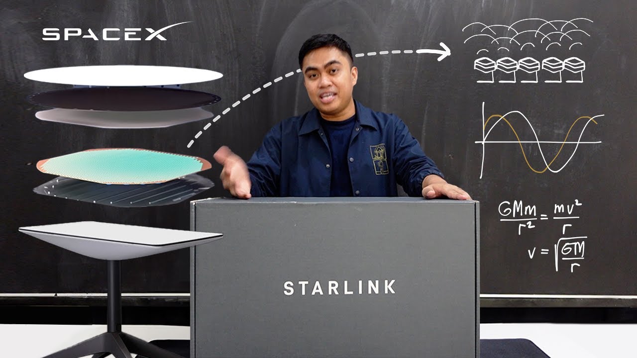
- 🛰️ Starlink uses a phased array satellite dish that both sends and receives internet data from low Earth orbit satellites, unlike traditional TV satellite dishes that only receive signals.
- 🚀 The Starlink satellites orbit at a much lower altitude of 550 kilometers compared to TV satellites at 35,000 kilometers, requiring precise and continuous beam steering to maintain connection.
- 🔄 The dish switches between different satellites every few minutes due to the fast movement of the satellites across the sky.
- 📡 Inside the Starlink dish, there's a sophisticated setup including motors, a PCB with microchips, and a massive array of 1280 antennas arranged in a hexagonal pattern for phased array communication.
- 📶 Each antenna in the array is controlled by microchips to generate and steer electromagnetic waves, creating a focused beam to communicate with the satellite.
- 🌐 The phased array uses beamforming to combine the signals from all antennas, resulting in a powerful beam capable of reaching the satellite in space.
- 🔧 Phased array beam steering is achieved by adjusting the phase of the signals sent to each antenna, allowing the beam to be directed towards the fast-moving satellite.
- 📈 The system uses GPS and software to calculate the precise angles and phase shifts needed for the antennas to maintain a lock on the satellite.
- 🔊 Data transmission between the dish and satellite utilizes 64QAM modulation, encoding 6-bit binary values with different amplitude and phase permutations, enabling high-speed data transfer.
- 🎥 The video codec h.264 is used to compress and transmit high-quality video data, allowing users to stream content smoothly.
- 👨🏫 The script highlights the multidisciplinary nature of the technology, touching on fields like electromagnetics, signal processing, and antenna design.
Q & A
What is the primary function of the Starlink satellite dish compared to a traditional TV satellite dish?
-The Starlink satellite dish, also known as Dishy McFlatface, both sends and receives internet data from a Starlink satellite orbiting 550 kilometers away, unlike traditional TV satellite dishes which only receive TV signals from broadcast satellites orbiting at an altitude of 35,000 kilometers.
How fast do the Starlink satellites move and what is the significance of their speed?
-Starlink satellites move at an incredible speed of around 27,000 kilometers per hour. This speed is significant as it allows for the rapid transmission of data at hundreds of megabits per second, despite the continuous need to angle or steer the data beam between the moving dish and satellite.
Why do Starlink satellites need to be in low Earth orbit?
-Starlink satellites are in low Earth orbit to provide low latencies of around 20 milliseconds, which is critical for activities such as online gaming or web browsing without noticeable delays.
What is the purpose of the phased array in the Starlink ground dish?
-The phased array in the Starlink ground dish is used to send and receive electromagnetic waves that are angled to and from a Starlink satellite. It consists of 1280 antennas arranged in a hexagonal honeycomb pattern, working together to focus the signal into a tight, powerful beam.
How does the phased array beam steering work in the Starlink dish?
-Phased array beam steering works by continuously changing the phase of the signals sent to the antennas, which alters the timing of the peaks and troughs emitted from each antenna. This creates a sweeping zone of constructive interference that can be directed towards the satellite.
What is the role of the motors in the Starlink dish during its operation?
-The motors in the Starlink dish are used only for initial setup to get the dish pointed in the proper general direction. They do not continuously move the dish to point directly at the Starlink satellite during operation.
How does the Starlink dish ensure it is communicating with the correct satellite?
-The Starlink dish uses its GPS coordinates and the known orbital position of the Starlink satellite. The software in the dish computes the exact set of 3D angles and required phase shift for each of the antennas to perfectly aim the beam at the satellite.
What is the maximum data transfer rate achievable with the Starlink system?
-The Starlink system can achieve a data transfer rate of up to 540 million bits per second using 64QAM (Quadrature Amplitude Modulation), which allows for the transmission of 6-bit binary values through different combinations of amplitude and phase.
How does the Starlink dish handle the transition between different satellites as they move out of its field of view?
-The Starlink dish switches between different satellites every 4 or so minutes as they move out of its field of view. This is managed by the dish's software, which constantly computes and updates the phase shifts required for communication with the next satellite in view.
What is the significance of the 100-degree field of view for the Starlink dish?
-The 100-degree field of view allows the Starlink dish to steer the beam in any direction within that range, ensuring continuous communication with the rapidly moving satellites without the need for physical movement of the dish.
How does the Starlink system minimize latency in data transmission?
-The Starlink system minimizes latency by distributing the time slots for data transmission throughout a single second, rather than grouping them all together. This ensures that the data is sent and received with minimal delay.
Outlines
🛰️ Starlink Satellite Internet Technology
This paragraph introduces the Starlink satellite internet system, highlighting its impressive technological feats. The system uses a large satellite dish, capable of transmitting data to satellites orbiting at 550 kilometers above Earth. The Starlink satellites move at an astonishing speed of 27,000 kilometers per hour, facilitating high-speed data transfer with minimal latency. The dish dynamically adjusts to maintain a direct connection with the rapidly moving satellites, switching between them every few minutes. The video promises an in-depth exploration of the technologies enabling this system, including the inner workings of the satellite dish, its ability to steer the data beam, and the data transmission capabilities that allow for simultaneous streaming of multiple HD movies.
🔍 Dissecting Dishy McFlatface and Its Antennas
The second paragraph delves into the technical differences between traditional TV satellite dishes and the Starlink ground dish, humorously named 'Dishy McFlatface.' Unlike TV dishes that only receive signals, Dishy sends and receives internet data. The Starlink satellite's lower orbit of 550 kilometers allows for faster data transmission but requires precise beam steering. The paragraph describes the internal components of Dishy, including its motors, ethernet cable, and the intricate printed circuit board (PCB) with microchips and GPS module. It also explains the phased array of 1280 antennas that work together to send and receive signals to the satellite, emphasizing the complexity and precision of the technology.
📡 Understanding Antenna Function and Beamforming
This paragraph explains the function of a single antenna within Dishy's phased array, focusing on the aperture-coupled patch antenna. It describes the process of generating an electromagnetic wave through the antenna's layers, including the microstrip transmission line feed and the antenna patch. The paragraph simplifies the complex process by illustrating how high-frequency signals create oscillating electric fields, leading to the formation of electromagnetic waves. It also touches on the antenna's ability to transmit and receive signals, the importance of phase shifting, and the concept of beamforming, which combines the power of multiple antennas to create a focused beam capable of reaching outer space.
🚀 Steering the Beam with Phased Array Technology
The fourth paragraph discusses the advanced technique of phased array beam steering, which is essential for maintaining a connection with the fast-moving Starlink satellite. It explains how phase shifting the signals sent to the antennas can angle the beam without physically moving the dish. The paragraph uses a simplified two-antenna example to demonstrate how constructive and destructive interference patterns can be manipulated to steer the beam. It also explains how Dishy uses GPS coordinates and software to calculate the necessary phase shifts for each antenna, allowing for precise beam direction and the ability to track satellites across a 100-degree field of view.
🌐 Data Transmission via 64QAM Modulation
The fifth paragraph explores how data is transmitted between Dishy and the Starlink satellite using 64QAM (Quadrature Amplitude Modulation). It describes the process of encoding binary data into variations of amplitude and phase, creating a constellation diagram with 64 different permutations. The paragraph explains how these symbols, each containing 6 bits of data, are transmitted in rapid succession, resulting in a high data transfer rate. It also discusses the division of transmission time between upload and download, and the distribution of these time slots to reduce latency.
📚 Conclusion and Further Exploration
The final paragraph wraps up the video script by acknowledging the complexity of the technology and the effort put into creating the video. It invites viewers to engage with the content through subscriptions, likes, and comments, and provides a link for further learning through Brilliant.org. The paragraph also clarifies some of the video's visual representations, emphasizing the actual scale of Dishy and the satellite, and the speed at which electromagnetic waves travel. It concludes by thanking sponsors and collaborators, and encourages viewers to explore more of Branch Education's content.
Mindmap
Keywords
💡Starlink
💡Satellite Dish
💡Phased Array
💡Beamforming
💡Parabolic Reflector
💡Orbital Position
💡Microchips
💡Quadrature Amplitude Modulation (64QAM)
💡Electromagnetic Waves
💡Constellation Diagram
Highlights
Beaming internet from the woods using a large satellite dish to a satellite 550 km away is a technological marvel.
Starlink satellites move at 27,000 km/h, with data speeds of hundreds of megabits per second.
The dish and satellite continuously angle to maintain a direct data beam connection.
The dish switches between different satellites every 4 minutes to maintain connectivity as they move out of view.
The video explores key technologies enabling satellite internet, including the satellite dish's inner workings.
Dishy McFlatface, the Starlink ground dish, both sends and receives internet data from orbiting satellites.
Starlink satellites are in low earth orbit for lower latency, requiring thousands for global coverage.
Dishy McFlatface contains 1280 antennas arranged in a hexagonal honeycomb pattern for phased array communication.
Each antenna in Dishy is controlled by microchips to generate and steer electromagnetic waves to the satellite.
Phased array beam steering uses phase shifting to angle the beam without physically moving the dish.
64QAM is used to encode 6-bit binary values into variations of amplitude and phase for data transmission.
The video provides a detailed explanation of how Dishy and the Starlink satellite communicate using electromagnetic waves.
The video explains advanced concepts in an accessible way, including the use of Brilliant for further learning.
The video clarifies misconceptions about the scale of Dishy and the satellite, and the speed of electromagnetic wave transmission.
The video script underwent extensive revisions to ensure accuracy and depth of information.
The video concludes with an invitation to support the creators and explore more technology through their animations.
Transcripts
Beaming internet from the middle of the woods using an extra-large pizza-sized
satellite dish placed on top of your house up to a satellite orbiting 550 kilometers outside
Earth’s atmosphere, well let’s be honest, is technologically mind-blowing. What’s even crazier
is that the Starlink satellites move incredibly fast, around 27,000 kilometers per hour,
and data is being sent back and forth between them at hundreds of megabits per second, all while the
dish and satellite are continuously angling or steering the beam of data pointed directly
between them. On top of that, the dish switches between different satellites every 4 or so minutes
because they move out of the dishes’ field of view rather quickly. If you have no clue as to
how this is possible, stick around because we’re going to dive into the multiple key technologies
which enable satellite internet to magically work. First, we’ll explore inside the satellite dish and
see how it generates a beam of data that is able to reach space. Second, we’ll see how this dish
continuously steers the beam so that it points directly at a satellite moving across the sky. And
third, we’ll dive into what exactly the dish and satellite are sending inside the beam that results
in your ability to stream five HD movies or shows simultaneously. This video is quite long as it’s
full of in-depth details. We recommend watching it first at one point two five times speed,
and then a second time at one and a half speed to understand it as a complete technology. So,
stick around, and let’s jump right in. First, let’s start by clarifying the
difference between a television satellite dish such as this one, and the Starlink ground dish,
which Elon Musk dubbed Dishy McFlatface or Dishy for short. TV dishes use a parabolic reflector
to focus the electromagnetic waves which are the TV signals sent from broadcast satellites
orbiting the Earth at an altitude of 35 thousand kilometers. TV satellite dishes only receive
TV signals from space, they can’t send data. Dishy, however, both sends and receives internet
data from a Starlink satellite orbiting 550 kilometers away. While the Starlink satellite is
60 times closer than TV satellites, it’s still an incredible distance to wirelessly send a signal,
and thus the beams between Dishy and the Starlink satellite need to be focused into tight powerful
beams that are continuously angled or steered to point at one another. Compare this to TV broadcast
signals which come from a satellite the size of a van, and whose signals propagate in a wide fan
that covers land masses larger than North America. Table size Starlink satellites,
however, need to be in a low earth orbit to provide for 20-millisecond latencies,
which is critical for smoothly playing internet games or surfing the web, and as a result, their
coverage is much smaller. Thus 10,000 or more Starlink satellites, all orbiting at incredibly
fast speeds in a low earth orbit, are required to provide satellite internet to the entire earth.
Let’s now open up Dishy McFlatface. At the back, we have a pair of motors and an ethernet cable
that connects to the router. Note that these motors don’t continuously move Dishy to point
directly at the Starlink satellite; they’re used only for initial setup to get the dish pointed in
the proper general direction. Opening up Dishy, we find an aluminum structural back-plate and on
the other side, we find a massive printed circuit board or PCB. One side has 640 small microchips
and 20 larger microchips organized in a pattern with very intricate traces
fanning out from the larger to smaller microchips, along with additional chips including the main CPU
and GPS module on the edge of the PCB. On the other side are 1,400ish copper circles with a grid
of squares between the circles. On the next layer, there’s a rubber honeycomb pattern with small,
notched cop-per circles, and behind that, we find another honeycomb pattern and then the front side
of Dishy. So, what are we looking at? Well, in essence, we have 1280 antennas arranged in a
hexagonal honeycomb pattern, with each stack of copper circles being a single antenna controlled
by the microchips on the PCB. This massive array works together in what’s called a phased array
in order to send and receive electromagnetic waves that are angled to and from a Starlink
satellite orbiting 550 kilometers above. Let’s zoom in and see how a single antenna operates.
Here we have an aperture coupled patch antenna composed of 6 layers, most of which are inside
the PCB. It looks very different from the antenna of an old-school radio, and is honestly,
incredibly complicated, so let’s simplify it. We’ll remove a few of the layers for now,
and step through the basic principles of how we generate an electromagnetic wave
that propagates out from this antenna. To start, at the bottom we have a microstrip
transmission line feed coming from one of the small microchips. This transmission line feed is
just a copper PCB trace or wire that abruptly ends under the antenna stack. We send a 12 Gigahertz
high-frequency voltage or signal to the feed wire which is a voltage that goes up and down
in a sinusoidal fashion, going from positive to negative and back to positive once every 83
pico-seconds, 12 billion times a second, or 12 Gigahertz. Note that high-frequency electricity
works differently from direct current or low frequency 50 or 60-hertz household electricity.
For example, above the copper feed wire, we have a copper circle with notches cut into it
called an antenna patch. With DC or low-frequency alternating current,
there wouldn’t be much happening because the patch is isolated, but with a high-frequency signal,
the power sent to the feed wire is coupled or sent to the patch. How exactly does this happen? Well,
as mentioned earlier, a 12 Gigahertz signal is applied to the copper feed wire. When the voltage
is at the bottom of its sinusoidal, or trough, we have a concentration of electrons pushed to
the end of the feed wire thus creating a zone of negative charge which corresponds to the maximum
negative voltage. This concentration of electrons on the tip of the wire repels all electrons away,
including the electrons on the top of the patch, and as a result, these electrons are pushed to
the other side of the circular patch. Thus, one side of the patch becomes positively charged,
while the other becomes negatively charged, thereby creating electric
fields between the patch and feed wire like so. However, when we reverse the voltage to the
copper feed wire 42 picoseconds later, we have a concentration of positive charges, or a lack of
electrons at the end of the wire, and thus the electrons in the patch flow to the other side,
the voltage in the patch is flipped, and the direction of the electric fields are also flipped.
Because the feed wire voltage oscillates back and forth, 42 picoseconds between one peak and trough,
the electric fields in the patch will also oscillate as the electrons, or current,
flows back and forth. If we pause the oscillation
we can see some of these electric field vectors, or arrows, from the patch, are vertical, and
because they are equal and opposite, they cancel out. However, other electric fields are horizontal
in the same plane of the patch and are called fringing fields. These fringing fields are in the
same direction and thus they add to each other, resulting in a combined electric field pointing
in this direction. At the same time, electrons flowing from one side of the disk to the other,
which is an electric current, generate a magnetic field with a strength and direction,
or vector, perpendicular to the fringing electric field vector. As a result,
we have an electric field pointing one way, and a magnetic field pointing perpendicular to that.
Let’s move forward in time to where the voltage on the feedline becomes positive,
and now, we’re at the peak of the sinusoid, 42 picoseconds later. The charge concentrations,
or voltage, as well as the current, is all flipped, and thus the electric and magnetic
fields point in the opposite directions. Electric and magnetic fields propagate in all directions,
and by creating these oscillating fields, we’ve generated an electromagnetic wave
which travels in the direction perpendicular to both the electric and magnetic field vectors.
Because the two sets of field vectors are not all in the same plane, but rather are curved, the
propagating electromagnetic wave travels outwards in an expanding shell or balloon-like fashion,
kind of like a light bulb on the ceiling. Let’s simplify the visual so we only see the peak and
trough or top and bottom of each wave and note that the trough is just a vector pointed in the
opposite direction. Additionally, the strengths of these field vectors directly relate back to
the voltage and signal that we originally sent to the copper microstrip feed wire at the bottom
of the stack. Which means, if we want to make these electric and magnetic fields stronger,
we just have to increase the voltage sent to the feedline. It’s like a dimmer on a light switch:
more power equals a brighter light. Thus far we’ve been talking about this
aperture-coupled patch-antenna as transmitting; however, it can also be used for receiving a
signal. In this microchip, called a front-end module, we switch the antenna from transmit to
receive and turn off the 12 Gigahertz signal. When an electromagnetic wave from the satellite
is directed towards Dishy, the electric fields from this incoming signal will influence the
electrons in the copper patch, thus generating an oscillating flow of electrons. This received
high-frequency signal is then coupled to the feedline where it’s sent to the front-end module
chip which amplifies the signal. Thus, these antennas can be used to both transmit and receive
electromagnetic waves, but, not at the same time. Two quick things to note. First, as seen earlier,
this antenna has many more layers and is more complicated than we’ve discussed. For example,
here are two circular patches. The bottom is used to transmit at 13 Gigahertz while the top
to receive at 11.7 Gigahertz. Additionally, there are two H slots and two feed wires to
support circular polarization, a reflective plane in the back, and also, there are multiple features
for isolating the operation of one antenna from the adjacent antennas. We’ve included these and
many more details in the creator’s comments which you can find in the English Canadian subtitles.
The second note is that there are electromagnetic waves of all different frequencies from
thousands of different sources passing through every point on Earth, whether it be visible
light from the sun, radio waves from radio or cell towers, or TV signals from satellites or
towers. Therefore in order to block out all other frequencies of electromagnetic waves,
these antenna patches are designed with very exact dimensions so that they receive
and transmit only a very narrow range of frequencies, and all the other frequencies
outside this range are essentially ignored by the antenna. Let’s move on and see how
a single antenna can be combined with others in order to amplify the beam to reach outer space.
This single antenna is only a centimeter or so in diameter and using only it would be
like turning on and off one light bulb and trying to see it from the international space station.
What we need is a way to make the light a few thousand times brighter, and then focus all the
electromagnetic waves into a single powerful beam. Enter the massive Mr. McFlatface PCB,
55 centimeters wide with a total of 1280 identical antennas in a hexagonal array. The
technique of combining all the antennas’ power together is called beamforming.
So how does it work? Well, let’s first see what happens when we have two simplified antennas
spaced a short distance away. As mentioned before, one antenna generates an electromagnetic wave that
propagates outwards in a balloon shape. At every single point in space, there’s only one electric
field vector with a strength and direction and thus the two antennas’ oscillating electric
field vectors combine together at all points in space. In some areas, the electric fields from
the antennas are pointing in the same direction with overlapping peaks, and thus add together via
constructive interference, and in other locations, they’re oppo-site with one peak and one trough,
and thus they cancel each other via destructive interference. We can now see that the zone where
they add together constructively is far tighter, or more focused, than a single antenna alone.
When we add even more antennas, the zone of constructive interference becomes even more
focused in what is called a beam front. Thus, by adding 1280 antennas together
we can form a beam with so much intensity and directionality that it can reach outer space.
Now you might be thinking that the strength of 1 antenna duplicated 1280 times over would result in
a combined power of, well, 1280 times a single antenna, but you’d be mistaken. The effective
power and range of the main beam from all these antennas combined is actually closer to 3500 times
that of a single antenna. The quick explanation is that by having these patterns of constructive
and destructive interference, it’s as if we took a single antenna, multiplied it by 1280,
and then placed a whole bunch of mirrors around it and left only a single hole for the main beam
to exit through. The long explanation requires a ton of math and physics, so let’s move on.
Dishy McFlatface and the Starlink Satellites undoubtedly have some rather complicated science
and engineering inside and to fully comprehend it all you have to be a multidisciplinary student.
To help you do that, check out Brilliant, which is sponsoring this video. Brilliant is an amazing
tool for learning. They teach a wide range of STEM topics in hands-on, interactive ways,
many of which directly relate to Starlink and other cutting-edge technologies such as
electric cars, quantum computers, rocketry, or neural networks. For example,
they have an entire course dedicated to Waves and Light, and another one on
gravitational physics which will greatly help in understanding Starlink and SpaceX rockets.
Brilliant is nothing like a boring textbook, but rather all the courses use interactive
modules to make the lessons entertaining and to help the concepts stick in your head.
To really understand today’s frontier technologies and to help you become a revolutionary engineer
and entrepreneur like Elon Musk, you have to be versed in a wide range of fields in
science and engineering. We recommend you sign up, try out some of the lessons for free and,
if you like them, which we’re sure you will, sign up for an annual subscription. To the viewers of
this channel, Brilliant is offering 20% off an annual subscription to the first 200 people who
sign up. Just go to brilliant.org/brancheducation. You can find that link in the description below.
Now let’s continue exploring how a powerful beam can be continuously swept across the sky,
and then how we fill it with hundreds of megabits of data every second.
As a quick refresher from before, here’s an array of 1280 antennas and we fed them
all with the same 12 Gigahertz signal in order to create a laser-like beam propagating perpendicular
to Dishy. However, as mentioned earlier, we need to be able to angle this beam so that it points
directly at the Starlink satellite zooming across the sky at 27,000 kilometers per hour.
Using the motors isn’t feasible because they would break within a month and aren’t accurate enough.
So, the solution is to use what’s called phased array beam steering.
Let’s go back to our two-antenna example. Before we were feeding
the same signal to the two antennas, and thus the antennas were in phase with one another.
Understanding phase is critical, so quickly: changing the height or amplitude of the signal
is done by changing the power sent to the antenna, thus making the signal stronger
or weaker. The frequency is how many peaks and troughs, or wavelengths there are in one second,
and changing the phase is shifting the signal left or right. Phase shifting is measured in degrees
between 0 and 359, because, if we shift the signal 360 degrees, or one full wavelength, then we’re
back at the beginning, exactly as if we were to loop around a circle. For example, here’s a signal
with a 45-degree phase shift, here’s another with a 180-degree shift, and then another with a
315-degree shift. Your eyes can’t see differences in phase shifted visible light, however, high-tech
circuitry such as what’s inside Dishy is really good at detecting and working with phase shifts.
So then, how do we use phase shifting to angle the beam and have it point directly at the satellite?
The solution is to phase shift the signal sent to one antenna with respect to the other antenna and,
as a result, the timing of the peaks and troughs emitted from one antenna is different from
the other. These peaks and troughs propagate outwards, and the location of the constructive
interference is now angled to the left with destructive interference everywhere else.
If we change the phase of the antennas again, the zone of constructive interference is angled to
the right. Therefore, by continuously changing the phase of the signals sent to the antennas,
we can create a sweeping zone of the constructive interference.
Let's bring in six more antennas and simplify the visual so that we only see a section of the
peaks from each wave. Far away from the antennas, the waves join to form a wave
front that is a planar wave. Kind of like ocean waves crashing on a shoreline. Just as before,
by continuously changing the timing of when each wave peak is emitted by each antenna,
we can change the angle at which the wave front is formed, essentially steering the beam in one
direction or another. And, if we bring in more antennas in a two-dimensional array,
we can now steer the beam in any direction within a one-hundred-degree field of view.
Let’s move back to view all 1280 antennas in Dishy. In order to know the exact angle the beam
needs to be pointed or steered, we use the GPS coordinates of Dishy from this chip over here,
along with the orbital position of the Starlink satellite which is known in Dishy’s software. The
software computes the exact set of 3D angles and the required phase shift for each of the antennas.
These phase shift results are then sent to the 20 larger chips called beamformers,
and each beamformer coordinates between 32 smaller chips called front end modules, each of which
controls 2 antennas. Every few microseconds, these computations are recalculated and disseminated to
all the microchips in order to perfectly aim the beam at the satellite. As a result, the beam can
be steered anywhere in a 100-degree field of view. There are a few quick notes. First, the main beam,
also called the main lobe looks like this. However, constructive and destructive
interference isn’t perfect, and as a result there are additional side lobes of lesser power.
Third, Mr. McFlatface holds is a single phased array, however, on the Starlink satellite,
there are in fact 4 phased array antennas. Two are used to communicate with multiple Dishys,
and 2 are used to communicate with the ground stations to relay the internet traffic.
And fourth, phased arrays are used in many applications, and interestingly they’re used
on commercial airlines to allow for mid-flight internet. So this video also tangentially
explains how mid-flight internet works. Before we explore how actual data is sent,
we want to mention that this video took a month to research, two dozen script revisions, and two
months to model and animate. If your mind is blown by the complexity of this technology and the depth
of this video click the subscribe button, like this video, write a comment below, and we’ll
be sure to create more videos like this one. The third topic we’re going to dive into is how
information gets sent between Dishy and the Starlink satellite. For example,
we’ve talked about high-frequency sinusoid-shaped electromagnetic waves,
but that doesn’t look anything like binary and even less like your favorite TV show.
So, what’s happening? Well, Dishy and the satellite indeed send a signal that looks like
this; however, they vary the amplitude and the phase of the transmitted signal and then assign
or encode 6-bit binary values to each different combination or permutation of amplitude and phase.
With 6 bits, there are 64 different values, and thus we need 64 different
permutations of amplitude and phase. However, instead of listing all the permutations,
it’s more easily visualized by arranging the 64 different values in a graph called a constellation
diagram as shown. Let’s look at the point 011 101 and draw a line from the origin to this point.
The distance from the origin is the amplitude of the signal, and the angle from the positive-X
axis is the phase. It’s a bit like using polar coordinates. Thus, for Dishy to send these 6-bits,
it transmits a signal with an amplitude of 59% and a phase shift of 121 degrees.
Then, if the next value being sent is 101 000, the signal switches to an 87% amplitude or brightness,
and a 305-degree phase shift. After that it sends the next value with a different amplitude and
phase shift. Each of these 6-bit groupings are called symbols and they last for only 10 or so
nanoseconds before the next symbol is sent. Lots of times you see the signal scrunched
up like this however, because the frequency of the signal is just once every 83 picoseconds,
or 12 Gigahertz, and since a symbol lasts 10 nanoseconds, it’s more accurate to have around
120 wavelengths per symbol before the next symbol is sent. Because we’re dealing on the order of
pico and nanoseconds, that means that we can fit 90 million 6-bit groups or symbols,
resulting in 540 million bits per second. However, note that this data transfer is shared between
download and upload. Since this particular antenna can’t transmit and receive data at the same time,
about 74 milliseconds of every second is used to send data from Dishy to the Starlink
satellite and 926 milliseconds is used to send data from the satellite down to Dishy. And,
for the sake of reducing latency, these time slots get distributed throughout a single second
instead of grouping them all together. This technique of sending 6-bit values
using different variations of amplitude and phase is called 64QAM or Quadrature Amplitude
Modulation and is more complicated than we discussed but let’s not get sidetracked.
Now that we have a stream of millions of 6-bit symbols yielding hundreds of megabits of data per
second, in order to turn it into your favorite TV show we use the advanced video codec, or
h.264 format. You can learn more about that in our video that explores image compression shown here.
I’m sure you have many questions, and by all means put them in the comments below,
but before we finish let’s clarify two things. First, the scale of practically everything in this
video is off. Here’s the correct scale of Dishy and the Starlink Satellite, however Dishy is 550
kilometers away which we can’t correctly show. In stark contrast, the emitted electromagnetic waves
are only around 2.5 centimeters apart, and thus between Dishy and the satellite there are around
22 million wavelengths which is many more than the few waves that you see here. Additionally, in this
animation we’re showing the wavelengths slowly making their way up and down, when in reality
it only takes around 2 milliseconds for an electromagnetic wave emitted from Dishy or
the Starlink satellite to reach the other. The second clarification is that we
disproportionately show Dishy emitting electromagnetic waves and sending them
to the satellite. In reality the satellite dish is more frequently in receive mode and the steps
and physics of receiving an electromagnetic wave are similar to emitting one, just in reverse.
That’s pretty much it for how Starlink and Dishy send data to each other. The original script for
this video was over 45 minutes long, so all the details that were cut got thrown in the creator’s
comments found in the English Canada subtitles. Thank you to all of our Patreon and YouTube
Membership Sponsors for helping to make this video. Also, thank you to Colin
O’Flynn at NewAE Technology for lending us a Starlink Dishy PCB for imaging and research.
This is Branch Education, and we create 3D animations that dive
deep into the technology that drives our modern world. Watch another Branch video
by clicking one of these cards or click here to subscribe. Thanks for watching to the end!
Weitere ähnliche Videos ansehen
5.0 / 5 (0 votes)