Sensor de presença - PIR ( Como funciona, com instalar e como usar)
Summary
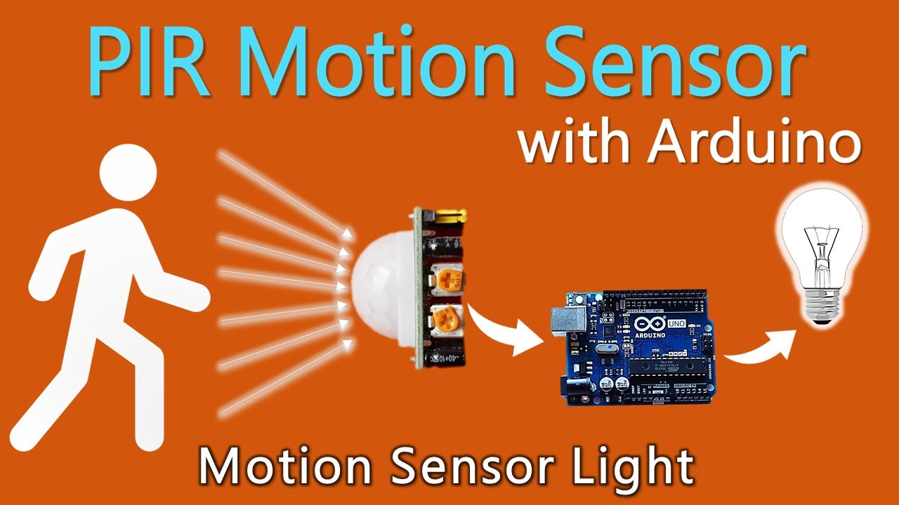
TLDRIn this video, the creator demonstrates how to build a motion-detecting light system using a motion sensor. The sensor, which operates on 5V, is connected to a circuit where it can detect movement and trigger the light to turn on. The video explains the sensor's components, how to set up the system, and how to adjust sensitivity and timing. For higher power, the creator uses a transistor to amplify the signal, allowing the system to power stronger LEDs. The tutorial is simple and provides clear instructions on creating a practical motion-activated light setup.
Takeaways
- 😀 The motion sensor has three main connections: VCC (power), GND (ground), and output (motion detection).
- 😀 The sensor operates on a voltage range from 4.5V to 12V, with 5V being the ideal input to avoid errors.
- 😀 The output of the sensor is typically 3V, which is not sufficient for powering high-intensity lights.
- 😀 The sensor's sensitivity and time settings can be adjusted to prevent false positives and control how long the light stays on.
- 😀 Always check the documentation of your specific sensor model to ensure correct pin connections and voltage ratings.
- 😀 To increase the light's brightness, a transistor (such as the 2N2222A) is used to amplify the power output to the LED.
- 😀 The base of the transistor is connected to the sensor's output through a 1kΩ resistor, which controls the LED's power.
- 😀 The emitter of the transistor is connected to ground, while the collector connects to the LED, allowing for a stronger current to pass.
- 😀 Use a resistor (e.g., 220Ω for regular LEDs or 33Ω for high-power LEDs) when connecting LEDs to prevent damage and control current.
- 😀 This setup enables multiple or stronger LEDs to be controlled effectively by the motion sensor, providing more lighting power.
- 😀 The sensor's output can turn on the lights immediately upon detecting movement, and can be configured to turn off after a set time period.
Q & A
What is the main goal of this tutorial?
-The main goal of the tutorial is to teach how to create a motion-activated light using a PIR (Passive Infrared) sensor, LED, and a transistor to amplify the power for brighter lights.
What components are required to complete the circuit?
-The components required include a PIR motion sensor, an LED (either blue or white), a transistor (2N2222A), resistors (220 ohms for regular LEDs or 33 ohms for high-power LEDs), a breadboard, and connecting wires.
How does the PIR sensor work in this circuit?
-The PIR sensor detects motion and outputs a 3V signal when movement is detected. This signal can then trigger a transistor to allow current to flow to the LED, thus turning the light on.
Why is the 3V output from the PIR sensor insufficient for powerful LEDs?
-The 3V output from the PIR sensor is too weak to power high-brightness LEDs, which is why the transistor is used to amplify the signal and power stronger LEDs.
What role does the transistor play in this circuit?
-The transistor acts as a switch, amplifying the signal from the PIR sensor and controlling the power supplied to the LED. It allows for higher-power LEDs to be used in the circuit.
How is the transistor connected to the PIR sensor and LED?
-The base of the transistor is connected to the output of the PIR sensor through a 1k resistor. The emitter is connected to ground, and the collector is connected to the LED circuit, which is also connected to a resistor before reaching the power supply.
What is the importance of using resistors in this circuit?
-Resistors are important to limit the current flowing through the circuit to prevent damage to components. For example, a 220-ohm resistor is used for regular LEDs, and a 33-ohm resistor is used for high-power LEDs.
What adjustments can be made on the PIR sensor?
-The PIR sensor has adjustable settings for both sensitivity and time. Sensitivity controls how much motion is required to trigger the sensor, and the time setting determines how long the light stays on after detection.
What is the recommended power supply for the PIR sensor?
-The recommended power supply for the PIR sensor is 5V, as it provides a safe and reliable voltage that works well with most PIR sensors without the risk of damage.
What is the best practice when working with various PIR sensor models?
-It’s important to check the datasheet or documentation for the specific PIR sensor model being used, as different sensors may have different pin configurations or voltage requirements.
Outlines

Dieser Bereich ist nur für Premium-Benutzer verfügbar. Bitte führen Sie ein Upgrade durch, um auf diesen Abschnitt zuzugreifen.
Upgrade durchführenMindmap

Dieser Bereich ist nur für Premium-Benutzer verfügbar. Bitte führen Sie ein Upgrade durch, um auf diesen Abschnitt zuzugreifen.
Upgrade durchführenKeywords

Dieser Bereich ist nur für Premium-Benutzer verfügbar. Bitte führen Sie ein Upgrade durch, um auf diesen Abschnitt zuzugreifen.
Upgrade durchführenHighlights

Dieser Bereich ist nur für Premium-Benutzer verfügbar. Bitte führen Sie ein Upgrade durch, um auf diesen Abschnitt zuzugreifen.
Upgrade durchführenTranscripts

Dieser Bereich ist nur für Premium-Benutzer verfügbar. Bitte führen Sie ein Upgrade durch, um auf diesen Abschnitt zuzugreifen.
Upgrade durchführenWeitere ähnliche Videos ansehen

Simulasi pemrograman arduino Uno menggunakan wokwi"Lampu otomatis menggunakan sensor gerak "

Cara buat saklar lampu otomatis SENSOR GERAK MANUSIA
How to use PIR Motion Sensor with Arduino | Motion sensor light

Automatic Lighting System with Arduino and PIR Sensor - Tinkercad Arduino Projects for Beginners

ESP32 Surveillance Camera | Send Images to Telegram - Work !!
How to make a Smoke detector Alarm | school science project smoke detector Alarm
5.0 / 5 (0 votes)
