TOP 5 Circuitos Electronicos OPTO Transistor⚡
Summary
TLDRThis video demonstrates how to use a transistor optocoupler to isolate circuits and control electronic components safely. It covers the setup of resistors, capacitors, and LEDs to polarize transistors, generate pulses, and manage voltage and current effectively. The tutorial explains how to visualize circuit behaviors through LEDs and manage timing with RC circuits. The speaker also shows how relays can control AC loads and discusses cascading transistors for expanded circuit control. This detailed guide helps viewers understand practical electronics applications while emphasizing efficiency and safety in circuit design.
Takeaways
- 😀 The optocoupler is capable of isolating up to 5000 volts per second, providing electrical safety and protection.
- 😀 A transistor can be used to control the optocoupler's LED, allowing for efficient light-based signal switching.
- 😀 The circuit operates with two different voltage levels: 6V for the transistor and 1.5V for the internal LED.
- 😀 The internal transistor can handle up to 1000mA of current and 80V, making it suitable for various applications.
- 😀 The system works with a 5V RAID setup, providing stable performance while isolating the components.
- 😀 Capacitors and resistors are used to generate RC timing circuits, which produce pulses for controlling the optocoupler.
- 😀 External components like a second transistor are used to enable cascading actions within the circuit, improving functionality.
- 😀 A visual indicator (LED) is placed in the collector of the internal transistor to show its switching state when light signals are received.
- 😀 The use of a relay enables the system to control AC loads without the need for additional high-power transistors.
- 😀 The script encourages users to explore further educational materials on electronics, including PDFs and online courses.
- 😀 The entire setup showcases how optocouplers and transistors can be used together for safe, efficient electrical signal control.
Q & A
What is the function of the transistor opto-coupler described in the script?
-The transistor opto-coupler, or optoisolator, is used to isolate electrical signals, allowing for the transfer of information between two circuits without direct electrical connection, while providing safety from high voltages.
What is the purpose of the resistance and negative connection in the transistor opto-coupler circuit?
-The resistance and negative connection are used to polarize the emitter of the internal transistor within the opto-coupler, ensuring the proper operation and emission of light when the circuit is activated.
How does the diode LED work in the described circuit?
-The diode LED in the circuit serves as an indicator, showing when the opto-coupler's transistor is activated. It can also function as part of the circuit to convert the signal from the internal transistor to a visible light signal.
Why is the circuit designed to work with two different voltages?
-The circuit is designed to operate with two voltages: one for the internal LED diode (1.5V) and another for the transistor (6V), allowing the transistor opto-coupler to work efficiently while maintaining safety and performance.
What is the significance of the 1000mA and 80V ratings mentioned for the internal transistor?
-The 1000mA (1A) current and 80V voltage ratings indicate the maximum power handling capability of the internal transistor in the opto-coupler, allowing it to work safely with moderate power levels without exceeding its limits.
How does the circuit handle the activation of an external load like a relay?
-The circuit can control an external load, such as a relay, by using the opto-coupler to isolate the control circuit from the power circuit, enabling safe activation of the load without requiring additional power transistors.
What role do the RC timing circuits play in the described system?
-The RC timing circuits are used to generate pulses or timing signals within the system. By controlling the timing of voltage changes, they help regulate the operation of the opto-coupler and external components like the diodes and transistors.
What does the use of an external bipolar transistor achieve in the circuit?
-The external bipolar transistor amplifies the signal received from the opto-coupler, enabling stronger current to flow and allowing the circuit to drive larger loads or control higher-power components.
What is the purpose of using two push buttons in the system?
-The two push buttons in the system are used to toggle between the positive and negative connections, allowing manual control of the circuit and enabling the opto-coupler to activate the internal and external transistors for signal switching.
How does the system demonstrate the switching of transistors?
-The system demonstrates the switching of transistors by lighting up an external LED diode when the transistor changes state. The LED visually shows when the internal transistor is activated by light or when its signal is obstructed, indicating the functioning of the circuit.
Outlines

Dieser Bereich ist nur für Premium-Benutzer verfügbar. Bitte führen Sie ein Upgrade durch, um auf diesen Abschnitt zuzugreifen.
Upgrade durchführenMindmap

Dieser Bereich ist nur für Premium-Benutzer verfügbar. Bitte führen Sie ein Upgrade durch, um auf diesen Abschnitt zuzugreifen.
Upgrade durchführenKeywords

Dieser Bereich ist nur für Premium-Benutzer verfügbar. Bitte führen Sie ein Upgrade durch, um auf diesen Abschnitt zuzugreifen.
Upgrade durchführenHighlights

Dieser Bereich ist nur für Premium-Benutzer verfügbar. Bitte führen Sie ein Upgrade durch, um auf diesen Abschnitt zuzugreifen.
Upgrade durchführenTranscripts

Dieser Bereich ist nur für Premium-Benutzer verfügbar. Bitte führen Sie ein Upgrade durch, um auf diesen Abschnitt zuzugreifen.
Upgrade durchführenWeitere ähnliche Videos ansehen

Belajar dan Membuat Sensor Suara untuk menyalakan Peralatan Listrik di Rumah | Project Sederhana

Informática - Aula 3 - Computadores: hardware
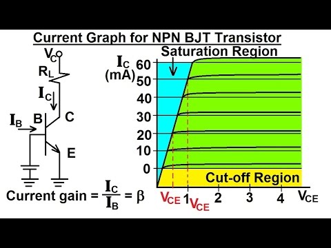
Electrical Engineering: Ch 3: Circuit Analysis (28 of 37) Current Graph for NPN BJT Transistor
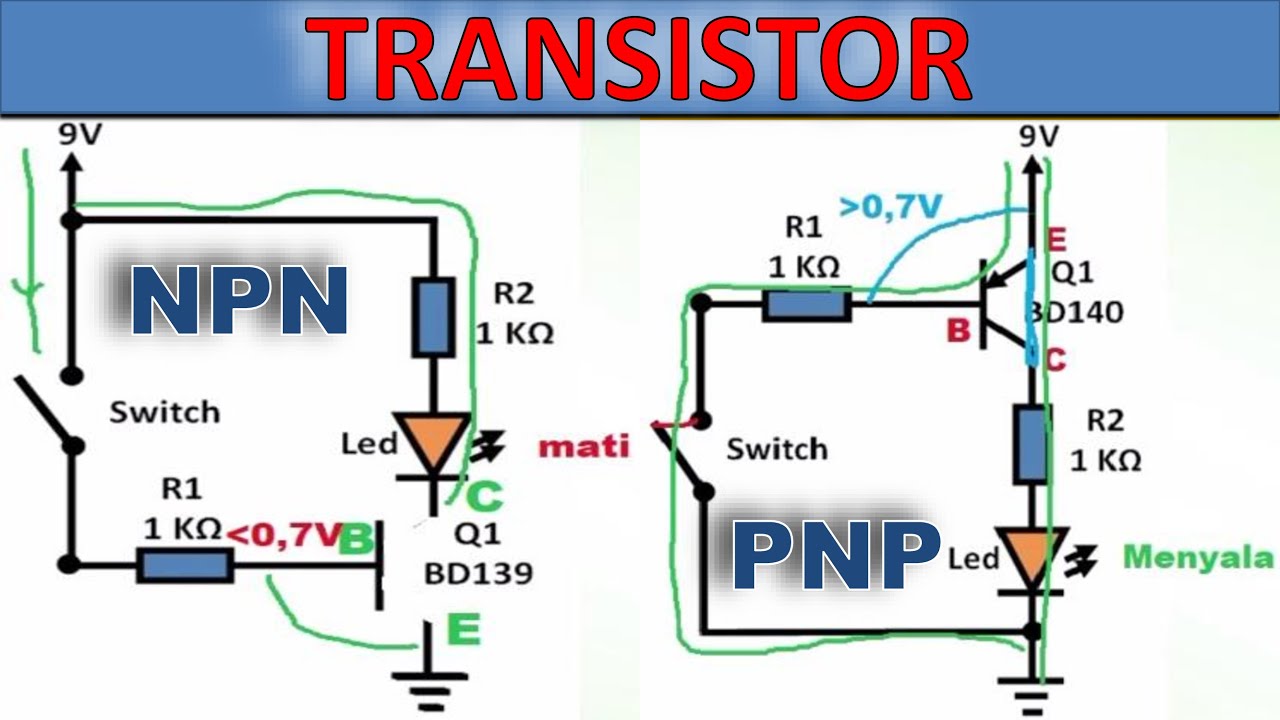
Penjelasan Transistor NPN dan PNP – Beserta contoh rangkaiannya

Constant Current Source with BJT Transistor

cara membuat pompa galon otomatis tanpa arduino / pompa galon elektrik
5.0 / 5 (0 votes)
