How 555 timers Work - The Learning Circuit
Summary
TLDRIn this episode of 'The Learning Circuit,' Karen explores the 555 timer, a versatile and popular IC in hobby electronics. She delves into the internal workings of the 8-pin chip, detailing its components like comparators, flip-flop, and voltage divider. Karen explains the function of each pin and how they interact to create a timer, oscillator, or flip-flop. The video promises a future episode on practical applications of the 555 timer in various circuit modes.
Takeaways
- 🌐 The 555 timer is a widely used integrated circuit (IC) in hobby electronics, known for its versatility in various applications.
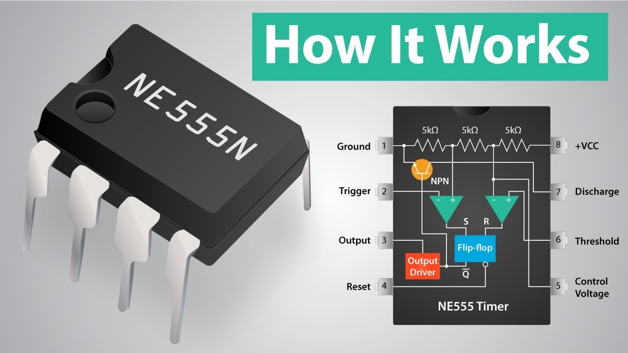
- 🔌 It features 8 pins, including ground (pin 1), trigger (pin 2), output (pin 3), reset (pin 4), control voltage (pin 5), threshold (pin 6), discharge (pin 7), and VCC (pin 8).
- 🏭 Inside the 555 timer, there are two comparators, a flip-flop, an inverter, two transistors, and a voltage divider made up of three 5kΩ resistors, which might be the origin of the '555' name.
- 🔋 The voltage divider divides the supply voltage (VCC) and feeds the comparators, with typical VCC values ranging from 5 to 15 volts.
- ⚖️ Comparators compare voltages at their inputs and output a digital signal indicating which input is larger, playing a crucial role in the 555's operation.
- 🔄 The flip-flop within the 555 timer is of the SR type, with set and reset inputs that control the output state, and only the NOT Q output is utilized.
- 🔧 The output of the flip-flop determines the state of the 555 timer's output pin, which is inverted before being outputted, creating a toggling effect.
- 🔩 Pin 5, the control voltage pin, can adjust the voltage at the negative input of comparator one, allowing for some control over the 555's operation.
- 🔄 Pin 4, when connected to VCC, ensures the 555 timer functions correctly; if grounded, it triggers a reset, causing the output to go low.
- 🔌 Pin 7, the discharge pin, is used with external capacitors to control the timer's duration, discharging the capacitor when the circuit is reset.
Q & A
What is the 555 timer and what is its primary function?
-The 555 timer is a widely used integrated circuit (IC) that functions as a timer, oscillator, or flip-flop. It is contained in an 8-pin IC and is popular in hobby circuits due to its versatility and ease of use.
How many pins does the 555 timer have and what are their typical functions?
-The 555 timer has 8 pins, which serve various functions: pin 1 is for ground, pin 2 is the trigger, pin 3 is the output, pin 4 is for reset, pin 5 is the control voltage, pin 6 is the threshold, pin 7 is the discharge, and pin 8 connects to VCC.
What are the main components inside the 555 timer?
-Inside the 555 timer, there are two comparators, a flip-flop, an inverter, two transistors, and a voltage divider made up of resistors.
How does the voltage divider inside the 555 timer work?
-The voltage divider is composed of three 56 kilo-ohm resistors and divides the supply voltage, feeding two comparators. It typically divides the VCC voltage so that one comparator receives two-thirds of the supply voltage and the other receives one-third.
What is the typical supply voltage range for the 555 timer?
-The typical supply voltage range for the 555 timer is from 4.5 to 16 volts, but VCC is usually between 5 and 15 volts.
How do the comparators in the 555 timer function?
-The comparators compare the voltages at their inputs and output a digital signal indicating which input is larger. If the positive input is larger, the output is high; if the negative input is larger, the output is low.
How does the flip-flop within the 555 timer contribute to its timing function?
-The flip-flop in the 555 timer has set and reset inputs that control its output. The flip-flop's output is used to control the timing function by setting and resetting based on the comparator outputs.
What is the purpose of the discharge pin (pin 7) on the 555 timer?
-Pin 7, the discharge pin, is used with external capacitors to control the timing duration of the timer. It connects to a transistor whose base is controlled by the flip-flop output, allowing the capacitor to discharge quickly when the circuit is reset.
How can the control voltage pin (pin 5) be used to modify the 555 timer's behavior?
-Pin 5, the control voltage pin, can be used to adjust the voltage at the negative input of comparator one, which typically receives two-thirds of VCC. This pin can be used to modify the timing behavior of the timer in certain applications.
What happens when both comparators in the 555 timer output high?
-When both comparators output high simultaneously, it is considered an invalid state because it causes the flip-flop's outputs to behave unpredictably. This situation should be avoided in proper circuit design.
Outlines
💡 Introduction to the 555 Timer
Karen introduces the 555 timer, a popular integrated circuit (IC) used in hobby circuits for its versatility as a timer, oscillator, or flip-flop. The video aims to demystify the inner workings of the 555 timer by examining its 8 pins: 1 for ground, 2 for trigger, 3 for output, 5 for control voltage, 6 for threshold, 7 for discharge, and 8 for VCC connection. The internal components are explored, including resistors, transistors, two comparators, a flip-flop, an inverter, and a voltage divider made from 3x 5k ohm resistors, which might be the origin of the '555' name. The voltage divider's function is explained, dividing the supply voltage into two-thirds and one-third for the comparators' inputs. The comparators' operation is detailed, with comparator one outputting high when the threshold pin (6) exceeds two-thirds VCC and comparator two outputting high when the trigger pin (2) is below one-third VCC. The flip-flop's role in the circuit is also explained, with its set and reset inputs controlling the output based on the comparators' signals.
🔄 Understanding the 555 Timer's Operation
This section delves deeper into the 555 timer's operation, focusing on the flip-flop's need to be reset to produce more than one timer tick. The process involves the trigger pin (2) going above three volts to reset the flip-flop, followed by the threshold pin (6) exceeding six volts to reset the flip-flop again. The importance of avoiding invalid states where both comparators output high is emphasized, as it leads to unpredictable behavior. The signal path from input to output is detailed, with the flip-flop's output passing through an inverter before appearing at pin 3. Additional pins' functions are explained: pin 5 for control voltage, which can adjust the comparators' input voltages, and pin 4 for resetting the circuit by grounding it. Lastly, pin 7's role in discharging external capacitors to control the timer's duration is discussed, with the explanation of how the flip-flop output controls the charging and discharging of the capacitor. The video concludes with a teaser for future episodes that will cover the 555 timer's applications in various circuit types and modes.
Mindmap
Keywords
💡555 Timer
💡Pin Configuration
💡Comparators
💡Flip-Flop
💡Voltage Divider
💡Control Voltage (Pin 5)
💡Reset (Pin 4)
💡Discharge (Pin 7)
💡Oscillator
💡Monostable and Bistable Modes
Highlights
Introduction to the 555 timer, a popular IC used in hobby circuits.
The 555 timer can act as a timer, oscillator, or flip-flop.
Description of the 8 pins of the 555 timer IC.
Explanation of the internal components of the 555 timer, including resistors, transistors, comparators, a flip-flop, and an inverter.
The voltage divider inside the 555 timer is made of three 5 kilo-ohm resistors, contributing to the IC's name.
The supply voltage is divided by the voltage divider to feed the comparators.
Comparators compare voltages and output digital signals indicating which input is larger.
How the flip-flop within the 555 timer is set and reset by the comparators.
The importance of not having both comparators output high simultaneously to avoid unpredictable behavior.
The role of the output pin in the 555 timer and how it is affected by the flip-flop's output.
The function of pin 5, the control voltage pin, and its impact on the comparator's input.
Pin 4's role in resetting the circuit and its connection to VCC.
The use of pin 7, the discharge pin, in conjunction with external capacitors to control the timer duration.
The charging and discharging of capacitors through pin 7 and its effect on the timer's operation.
Upcoming episode teaser on how the 555 timer can be used in various circuit types and modes.
Invitation for viewers to join the element14 community for further learning and support.
Transcripts
the following program is brought to you
by element14 the electronics community
where you can connect and collaborate
with top engineers from around the world
join now at element14.com slash presents
hi and welcome back to the learning
circuit
I'm Karen and today we're going to learn
about a very useful I see the 555 timer
[Music]
the 555 timer is one of the most popular
ICS to use in hobby circuits it's easy
to find schematics that show any one of
the numerous ways to use the 555 but to
better understand how they work in
circuits I want to talk about what's
happening inside the 5 5 5 the 5 5 5
timer is a switching circuit contained
in an 8 pin IC that can act as a timer
oscillator or flip-flop let's take a
look at those 8 pins as usual
we can find pin 1 to the left of the
notch or dot on the surface of the chip
pin 1 is for ground 2 is the trigger 3
the output for reset 5 control voltage 6
threshold 7 discharge an 8 for
connecting to VCC we can look at what's
inside the 555 to explore what all those
pins do the 555 is made up of resistors
and transistors but those can be broken
up into various main components here's a
block diagram of those components inside
the 555 there are two comparators a
flip-flop and inverter two transistors
and a voltage divider looking closer at
the voltage divider you can see that it
is made of 3 5 kilo ohm resistors some
believe this is where the 5 i5 gets its
name the voltage divider is connected to
power and ground dividing the supply
voltage and feeding the two comparators
since the resistors are all the same
value the supply voltage or VCC is
divided with the input of comparator 1
getting two thirds supply voltage and
the input of comparator two getting one
third supply voltage while the supply
voltage range is typically four point
five to 16 volts VCC is usually between
5 and 15 volts let's say our circuit is
running on a 9-volt battery therefore
VCC is 9 volts from the voltage divider
the negative input of comparator 1 would
be 2/3 of that 6 volts while the
positive input of comparator 2 would be
1/3 of that 3 volts the positive second
input of comparator 1 goes to pin 6 the
threshold and the negative second input
of comparator 2 goes to pin 2 the
trigger a comparator is a device that
compares the voltages at its inputs and
outputs a digital signal indicating
which of its inputs is larger
positive input is larger the output is
high if the negative input is larger the
output is low let's take a look at
comparator one the positive input is
connected to pin six threshold and the
negative input is connected to the
voltage divider with nine volts VCC the
negative input has six volts well the
negative input at six volts is larger
the comparator will output low but if
the voltage at pin six is larger above
six volts the comparator will output
high if pin six ever drops below six
volts making the negative input larger
the comparator output would revert back
to low now let's take a look at
comparator two on this comparator the
positive input is connected to the
voltage divider getting 1/3 of VCC so
with nine volts VCC that makes the input
three volts the negative input goes to
pin 2 the trigger if the voltage at that
pin is below three volts the output goes
high
if pin two goes above three volts
becoming the larger input the output
would go low and again as soon as pin
two drops below three volts the output
will revert to high the outputs of the
comparators go to the two inputs of the
flip-flop in a previous episode I
covered how SR flip-flops work but I'll
recap that for you real quick the
flip-flop has two inputs set and reset
marked by s and R and two outputs Q and
not Q naught U is always the inverse of
Q this SR flip-flop is active hi the set
input sets the output high while the
reset input resets the output back to
low when set goes high output Q goes
high with not Q being the inverse if
both inputs are low the outputs don't
change when reset goes high output Q
goes low with not you being the inverse
while flip-flops typically have two
outputs in the 555 timer only output not
Q is used let's look at our comparators
in action and how they set and reset the
flip-flop VCC is still nine volts pin
six needs to be lower than six volts for
comparator one toutput low when pin two
is lower than three
volts comparator two outputs hi this
sets the flip-flop and not Q output slow
the trigger at pin two acts like a
starter pistol starting the timer
setting the flip-flop but in order to
get more than one tick of the timer the
flip-flop needs to first be reset first
the voltage at pin two must go higher
than three volts so that compared to two
outputs low then when pin six goes
higher than six volts comparator one
outputs high this resets the flip-flop
and not Q goes high we learn in the flip
flop episode that we never want both
inputs SNR to go high at the same time
when that happens the outputs begin to
behave unpredictably so we never want
pin six to go high and pin two to go low
causing both comparators to output high
at the same time this state is
considered invalid so now the flip-flop
is outputting a digital signal high or
low and this goes to the output pin of
the 5-5-5 timer
first the signal passes through an
inverter then out to pin three this
effectively outputs what would be the
signal from output Q of the flip-flop
that covers the path of the signal from
input to output but we still have three
pins to cover pin five is control
voltage they connect to the negative
input of comparator one typically this
input has a voltage that's two-thirds
VCC but pin five can be used to adjust
or control that voltage in some use
cases it's ideal to have an easy way to
reset the circuit so we have pin four
pin four is connected to the base of a
transistor this transistor must be on
for the five high five to function so
pin four is usually connected to VCC to
hold it high if pin four is ever
grounded going low the transistor is
turned off this triggers the reset and
the five by five output goes low last is
pin 7 discharge it's used with external
capacitors that are integral in studying
the duration of the timer in the five
five five pin seven is connected to
another transistor whose base is
controlled by the flip-flop output when
the five five five output is high not Q
is low so the transistor is off this
usually causes the capacitor to charge
up and eventually triggers the reset
when the circuit is reset the transistor
turns on which connects the capacitor to
ground allowing it to quickly discharge
I've covered how the 555 timer works
internally but to fully understand how
some of the pins function they need to
be seen working in a circuit so in a
future episode I'm going to talk about
how the 555 timer can be used in various
types of circuits and modes like a
stable monostable and by stable if you
have any questions about what we learned
today
you can get help by posting to the
element14 community on element14.com
forward slash the learning circuit happy
learning
[Music]
you
Weitere ähnliche Videos ansehen
How Integrated Circuits Work - The Learning Circuit
555 Chip Explained - LED Blinker, Buzzer, Siren...
Off Delay Timer | how to make off delay timer | how to make delay timer | delay timer
How Do Ultrasonic Distance Sensors Work? - The Learning Circuit
How Laser Diodes Work - The Learning Circuit
Essential Electronics Components that you will need for creating projects!
5.0 / 5 (0 votes)