UML use case diagrams
Summary
TLDRIn this tutorial, Collin introduces UML use case diagrams, a powerful tool to visualize and communicate system interactions. He explains key elements, such as systems, actors, use cases, and relationships, and provides a step-by-step guide to creating a use case diagram using Lucidchart. The video explores the differences between primary and secondary actors, includes detailed explanations of relationship types like association, include, extend, and generalization, and offers practical examples using a banking app. The goal is to help viewers grasp how to create clear and effective diagrams to illustrate system behavior and interactions.
Takeaways
- 😀 A UML use case diagram is a high-level representation of how a system interacts with users or other systems to achieve specific goals.
- 😀 The main components of a use case diagram include systems, actors, use cases, and relationships.
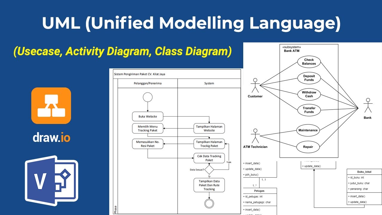
- 😀 Systems are represented by rectangles and define the scope of the application or process being diagrammed.
- 😀 Actors are external entities (people, organizations, or other systems) that interact with the system to achieve a goal, depicted by stick figures outside the system rectangle.
- 😀 Primary actors initiate the system's use, while secondary actors respond or support the primary actor's actions.
- 😀 Use cases represent specific tasks or actions the system performs, displayed in ovals within the system's rectangle.
- 😀 Relationships, such as associations, show how actors interact with use cases and are depicted by solid lines between actors and use cases.
- 😀 An include relationship occurs when one use case always requires another to complete, represented by a dashed line with an arrow pointing to the included use case.
- 😀 An extend relationship is optional, where a use case may or may not trigger an extended action based on conditions, shown by a dashed line pointing to the base use case.
- 😀 Generalization allows for creating specialized use cases or actors, where the child elements inherit the behavior of the parent, indicated by an arrow pointing from child to parent.
- 😀 Simple, clear diagrams are essential for conveying complex system behaviors, and tools like Lucidchart help in creating effective use case diagrams.
Q & A
What is the purpose of a UML use case diagram?
-A UML use case diagram visually represents the interactions between a system and its actors, showing the flow of tasks or actions within the system. It helps communicate complex ideas in a simple and clear way.
What four elements are essential to a UML use case diagram?
-The four essential elements of a UML use case diagram are systems, actors, use cases, and relationships.
How is a system represented in a use case diagram?
-A system is represented by a rectangle in a use case diagram, with the system's name placed at the top of the rectangle. This rectangle defines the scope of the system.
What is the role of an actor in a use case diagram?
-An actor is any person, organization, system, or device that interacts with the system to achieve a goal. Actors are depicted by stick figures and are placed outside the system boundary.
How do primary and secondary actors differ in a use case diagram?
-A primary actor initiates the use of the system, while a secondary actor reacts to actions taken by the primary actor. For example, in a banking app, the customer is a primary actor, while the bank is a secondary actor.
What is a use case, and how is it represented in a UML diagram?
-A use case is an action or task that the system performs to achieve a goal. It is represented by an oval shape within the system boundary and typically starts with a verb to describe the action.
What is the purpose of the association relationship in a use case diagram?
-The association relationship shows the interaction between an actor and a use case. A solid line is drawn between the actor and the use case to represent communication or action.
What are the three additional types of relationships in a use case diagram, and what do they signify?
-The three additional types of relationships are include, extend, and generalization. An 'include' relationship shows that one use case always includes another; an 'extend' relationship shows optional actions that occur under certain conditions; and a 'generalization' relationship signifies inheritance or specialization between use cases or actors.
How does the include relationship differ from the extend relationship?
-An 'include' relationship is mandatory and always occurs when the base use case is executed. In contrast, an 'extend' relationship is optional and only occurs under specific conditions, depending on the situation.
Can use cases share relationships with multiple base use cases? How?
-Yes, use cases can share relationships with multiple base use cases. For example, both 'transfer funds' and 'make payment' can point to the same 'verify sufficient funds' use case, which ensures that this verification happens every time either of these base use cases is executed.
Outlines

هذا القسم متوفر فقط للمشتركين. يرجى الترقية للوصول إلى هذه الميزة.
قم بالترقية الآنMindmap

هذا القسم متوفر فقط للمشتركين. يرجى الترقية للوصول إلى هذه الميزة.
قم بالترقية الآنKeywords

هذا القسم متوفر فقط للمشتركين. يرجى الترقية للوصول إلى هذه الميزة.
قم بالترقية الآنHighlights

هذا القسم متوفر فقط للمشتركين. يرجى الترقية للوصول إلى هذه الميزة.
قم بالترقية الآنTranscripts

هذا القسم متوفر فقط للمشتركين. يرجى الترقية للوصول إلى هذه الميزة.
قم بالترقية الآنتصفح المزيد من مقاطع الفيديو ذات الصلة


5.0 / 5 (0 votes)
