ML-122X Devreye Alımı: Tesisat Kontrolü
Summary
TLDRThis video script is an educational guide for the ML120 2x smart addressable fire alarm system. It covers essential pre-operation checks such as wire breakage, short circuits, and grounding issues. The video emphasizes the importance of resolving these problems before system operation. It outlines the specifications for the wiring, including the maximum length for 0.8 mm² and 1.5 mm² wire gauges. The script also discusses the process of identifying and fixing short circuits and grounding issues through project tracking and field reduction methods. Lastly, it explains how to perform voltage measurements for ground leakage, highlighting the acceptable voltage range and the significance of staying within specified tolerances to ensure system integrity.
Takeaways
- 🔍 Conduct thorough checks for open circuits, short circuits, and ground leakage before operating the ML120 2x Smart Addressed Fire Alarm system.
- 🛠 Ensure that the ring circuit wire used in the system is not longer than 1200 meters for a 0.8 mm² cross-sectional area, and not longer than 1500 meters for a 1.5 mm² cross-sectional area.
- 🔌 Check for continuity and proper connections in the ring circuit wiring, including the screen wire, to avoid open circuit issues.
- 🔍 Perform line checks to identify any open circuits by tracing the project and narrowing down the area with the fault.
- 🔌 Ensure that there are no missing connections in the ring circuit wiring, as this indicates an open circuit that needs to be resolved.
- 🔍 When checking for short circuits, verify that there is no direct connection between the positive and negative wires, the screen wire, and the earth wire in the circuit.
- 🛠 If a short circuit is detected, connections need to be made to the control center to resolve the issue.
- 🔌 In ground leakage checks, ensure that the positive and negative wires of the circuit do not touch water or ground through the ceiling, walls, or similar points.
- 🔧 Correct any identified points where the wires are touching water or ground to prevent ground leakage.
- 🔋 Measure the external voltage of the control center's 24V DC series with a measuring instrument, which should be within the range of 12.30 to 13.50 volts.
- ⚠️ If the measured external voltage deviates more than 20 millionths from the specified range, it indicates a ground fault that needs to be addressed.
Q & A
What is the main topic of the video script?
-The video script is about the installation and troubleshooting of an ML120 2x smart addressable fire alarm system.
What are the initial checks required before operating the fire alarm system?
-Before operating the system, it is necessary to check for open circuits, short circuits, and ground leakage to ensure there are no issues.
What is the recommended cross-sectional area for the circuit wire used in the system?
-The recommended cross-sectional area for the circuit wire is 0.8 millimeters for a maximum length of 1200 meters, and 1.5 millimeters for a maximum length of 100 meters.
What should be checked during the circuit installation?
-During circuit installation, it is important to check for any missing connections, reversals of positive to negative and vice versa, and the presence of a screen cable in the circuit.
What does it mean if there is a missing connection in the circuit?
-A missing connection in the circuit indicates a wire breakage, which is a problem that needs to be resolved.
How is a wire breakage or short circuit identified in the project?
-Wire breakages or short circuits are identified by following the project and using a narrowing method to locate the faulty cable or connection point.
What checks should be performed during a short circuit inspection?
-During a short circuit inspection, one should check for any shorts between the positive and negative, between the screen and the positive, and between the screen cable and the ground.
What is the acceptable voltage range for the external voltage measurement?
-The acceptable external voltage range is between 12.30 to 13.50 volts, with a tolerance of plus or minus 20 millionths.
What does it indicate if the measured external voltage deviates more than the specified tolerance?
-If the measured external voltage deviates more than the specified tolerance, it indicates a ground fault that needs to be corrected.
How is a ground leakage issue identified and resolved?
-A ground leakage issue is identified by following the project and using a narrowing method to locate the cable or connection point with leakage. The identified points must be corrected.
What is the final call to action for viewers in the video script?
-The final call to action is to subscribe to the channel for more information.
Outlines

Dieser Bereich ist nur für Premium-Benutzer verfügbar. Bitte führen Sie ein Upgrade durch, um auf diesen Abschnitt zuzugreifen.
Upgrade durchführenMindmap

Dieser Bereich ist nur für Premium-Benutzer verfügbar. Bitte führen Sie ein Upgrade durch, um auf diesen Abschnitt zuzugreifen.
Upgrade durchführenKeywords

Dieser Bereich ist nur für Premium-Benutzer verfügbar. Bitte führen Sie ein Upgrade durch, um auf diesen Abschnitt zuzugreifen.
Upgrade durchführenHighlights

Dieser Bereich ist nur für Premium-Benutzer verfügbar. Bitte führen Sie ein Upgrade durch, um auf diesen Abschnitt zuzugreifen.
Upgrade durchführenTranscripts

Dieser Bereich ist nur für Premium-Benutzer verfügbar. Bitte führen Sie ein Upgrade durch, um auf diesen Abschnitt zuzugreifen.
Upgrade durchführenWeitere ähnliche Videos ansehen

BASIC OF FIRE ALARM SYSTEMS ( DASAR-DASAR SISTEM DETEKSI KEBAKARAN) - PART 6
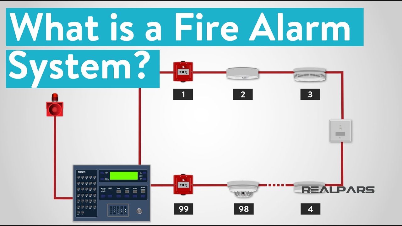
What is a Fire Alarm System?

Alarme e Detecção
How to make a Fire Alarm System using Arduino Uno
Smart Home Dashboard with ThingsBoard & ESP32: Real-Time Monitoring, Device Control, IP Cam & Alerts
(Proteus) Tutorial Membuat Alat Pendeteksi Maling dengan Alarm Penjebak
5.0 / 5 (0 votes)
